

Brazing repairs
a gas turbine engine and brazing technology, applied in the direction of manufacturing tools, turbines, slendering apparatus, etc., can solve the problems of significant rework and/or scrappage, compromising structural properties, and joint defects in the brazing
- Summary
- Abstract
- Description
- Claims
- Application Information
AI Technical Summary
Problems solved by technology
Method used
Image

Examples
Embodiment Construction
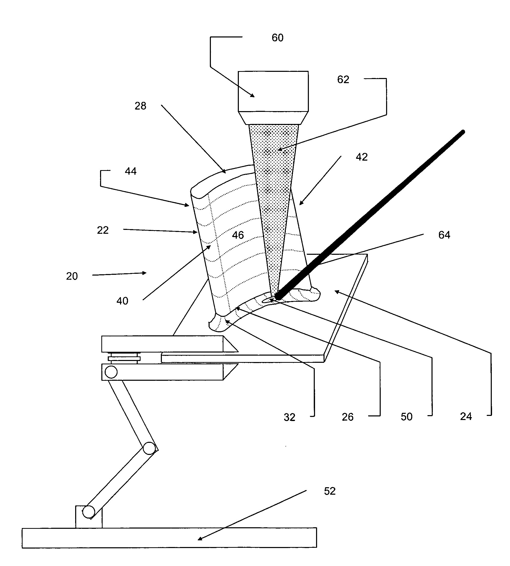
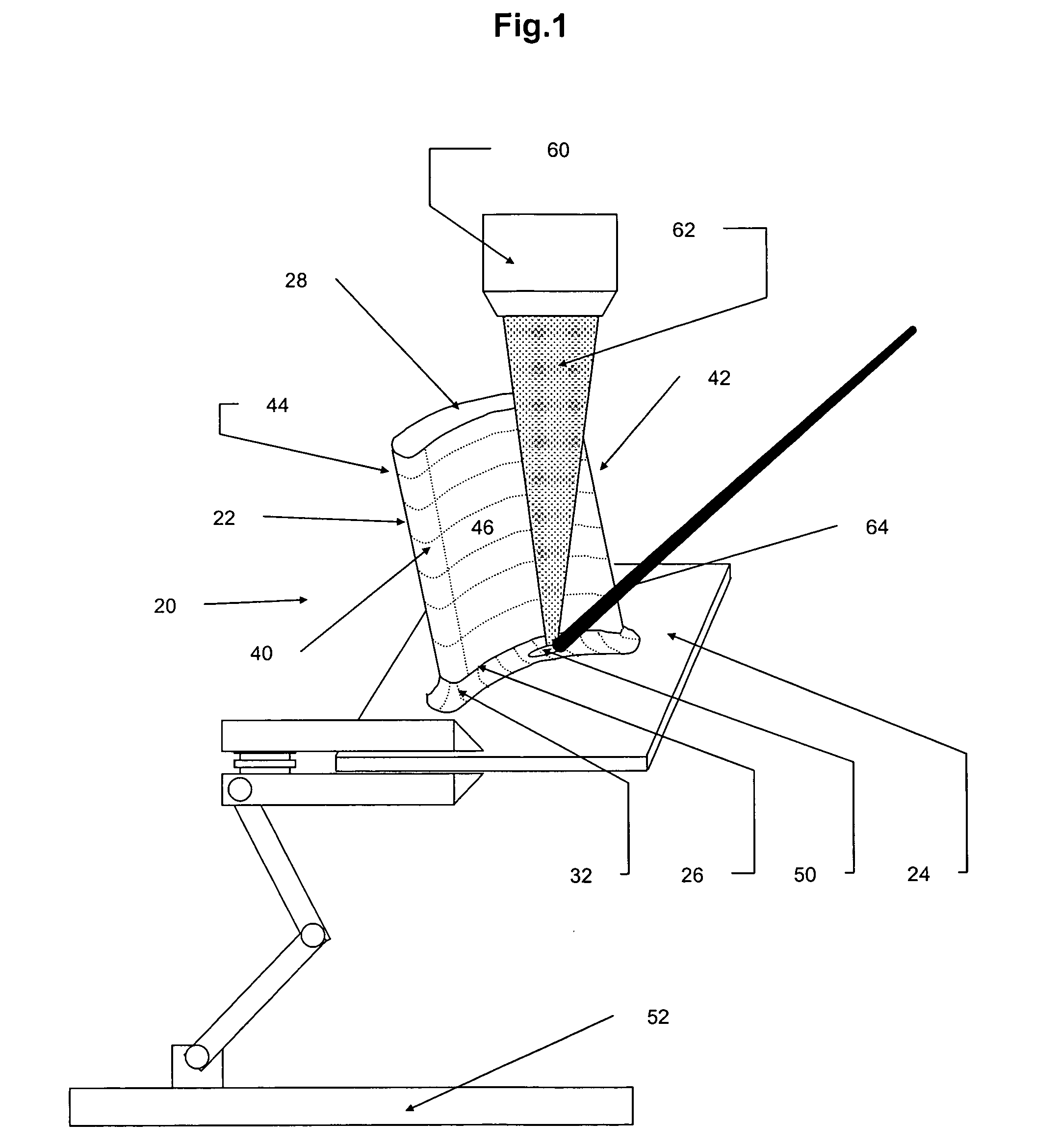
[0010]FIG. 1 shows a vane 20 undergoing a braze touch-up. The vane 20 has an airfoil 22 and an OD shroud 24. The airfoil 22 has an outboard end 26 and an inboard end 28. Adjacent the outboard end 26, the airfoil 22 is secured to the shroud 24 by a bulk fillet braze 32. The airfoil 22 has a leading edge 40, a trailing edge 42, a suction side surface 44, and a pressure side surface 46. The vane is slid through a hole of similar geometry in the shroud and the exemplary braze 32 circumscribes the airfoil essentially along an entirety of the pressure and suction sides on the ID and OD faces of the shroud. The exemplary braze 32, however, may be initially formed with a defect 50 (e.g., a through-void). The presence of the defect 50 may be detected in an inspection (e.g., an automated inspection such as an X-ray inspection) or a manual visual inspection. The location of the defect(s) may be noted and / or recorded. The vane 20 may be placed in a repair fixture 52 (e.g., a three-axis position...
PUM
| Property | Measurement | Unit |
|---|---|---|
| Temperature | aaaaa | aaaaa |
| Composition | aaaaa | aaaaa |
| Perimeter | aaaaa | aaaaa |
Abstract
Description
Claims
Application Information