Table component assembly

Inactive Publication Date: 2008-02-07
LEE SHAW MING
View PDF3 Cites 6 Cited by
  • Summary
  • Abstract
  • Description
  • Claims
  • Application Information

AI Technical Summary

Benefits of technology

[0004]Because the combining units of the prior art of the traditional hollow tube are exposed out of the table body whiling assembling, the appearance quality of the table is reduced and the exposure causes the assembly table unsafely.
[0005]The secondary primary objective of the present invention is to assure the positio

Problems solved by technology

Because the combining units of the prior art of the traditional hollow tube are exposed out of the table body whil

Method used


Image

  • Table component assembly
  • Table component assembly
  • Table component assembly

Examples


Embodiment Construction

[0021]In order that those skilled in the art can further understand the present invention, a description will be described in the following in details. However, these descriptions and the appended drawings are only used to cause those skilled in the art to understand the objects, features, and characteristics of the present invention, but not to be used to confine the scope and spirit of the present invention defined in the appended claims.

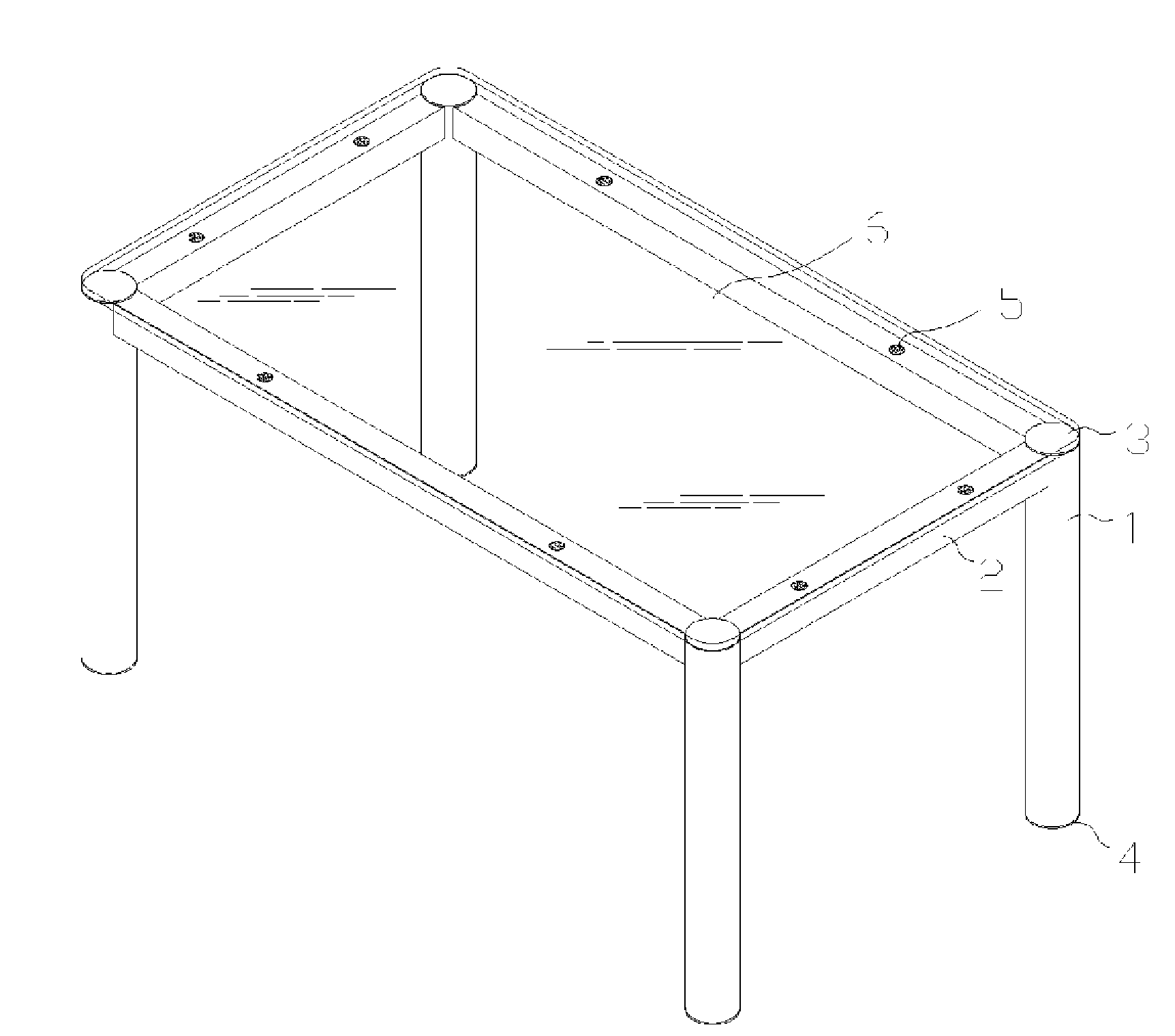
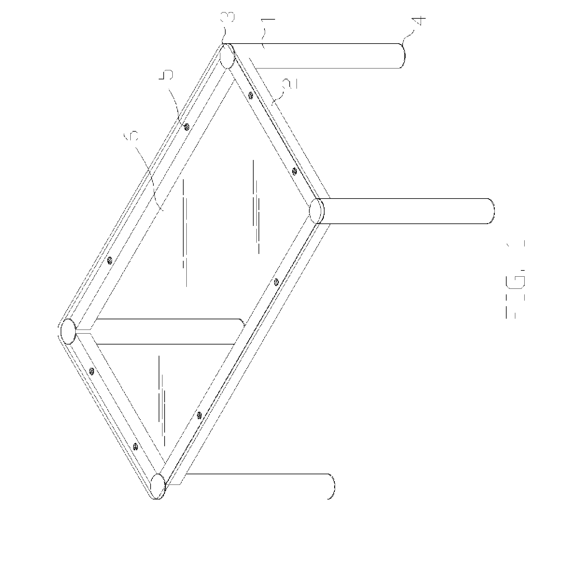
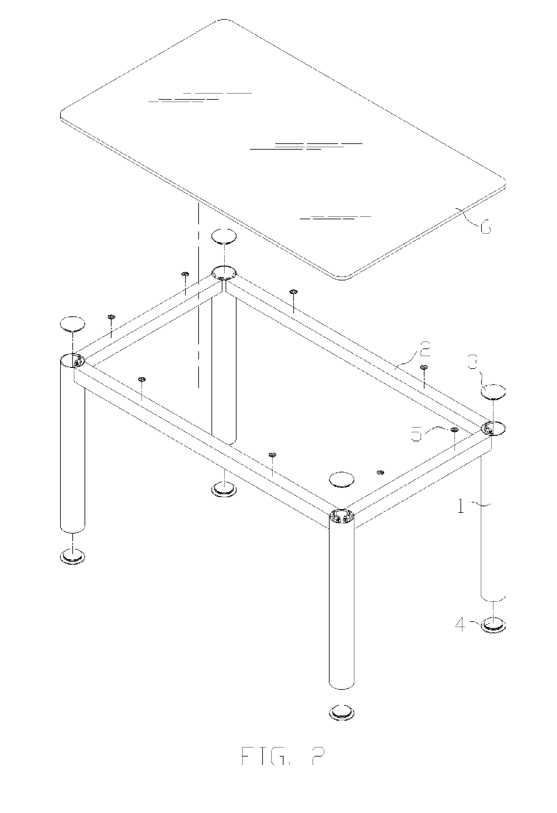
[0022]Referring to FIG. 1, a table main body is assembled by four leg21 with round tube shapes and four beams 2. A plurality of slide stop pads 5 are placed suitably on four table beams so as to provide enough friction force for a glass plate 6. The glass plate 6 as a tabletop is free from arbitrarily movement.

[0023]Referring to FIG. 2, a table leg cover 3 is covered on the leg 1 for a purpose of improving table appearance. Besides, a table leg pad 4 is installed on the bottom of the leg 1 so that the table leg pad 4 can not only prevent from tabl...


PUM


Abstract

An assembly table has a leg of a round tube, a beam, a combining unit, and wherein a table body is assembled by the upper end of the leg by using of the combining unit to combine the beam. The leg is a hollow tube. The straight positioning holes are opened at the upper end of the leg and serves to combine the combining unit. Each side of the straight positioning hole has one enhancing body. The beam is a hollow tube. The each end of the beam has a combining unit. The combining unit is welded directly to the hollow tube of the beam. The combining unit has a substrate, a stud, a washer, a nut and a positioning pin. The stud and the positioning pin are fixed firmly on the substrate. The washer is looped on the stud. The nut is screwed in the stud.

Description

FIELD OF THE INVENTION[0001]The present invention relates to table assemblies, and in particular to a table component assembly which is capable of fast positioning the components of the table and hiding the components of combining units.BACKGROUND OF THE INVENTION[0002]A prior art of a table component assembly is difficult not only to position table components, but also to expose combining units thereof. Therefore, the assembly table of the prior art is not so beautiful as well as unsafe. The combing perpendicularity of the leg and the beam of the prior art is usually lack of accuracy and the adjusting the combining perpendicularity takes so much time. Sometimes, the leg and the beam is incapable of being screwed tightly causing to rotating relatively thereof so as to influence the stability of the assembly table.SUMMARY OF THE INVENTION[0003]The primary objective of the present invention is to assure the appearance at higher quality. Besides, all the combining units are hidden in t...

Claims


Application Information

Patent Timeline
IPC IPC(8): A47B97/00
CPCF16B12/52
Inventor LEE, SHAW-MING
Owner LEE SHAW MING
Why Eureka
Try Eureka