Inspection method, inspection apparatus, and polarization method for piezoelectric element

a piezoelectric element and inspection apparatus technology, applied in the direction of generators/motors, instruments, printing, etc., can solve the problem of erroneously determining normality of piezoelectric elements which are actually anomalous, and achieve the effect of rapid progressing reducing the risk of polarization, and increasing the polarization of piezoelectric elements

Inactive Publication Date: 2008-02-07
NGK INSULATORS LTD
View PDF7 Cites 25 Cited by
  • Summary
  • Abstract
  • Description
  • Claims
  • Application Information

AI Technical Summary

Benefits of technology

[0006] Accordingly, one of objects of the present invention is to provide an inspection method for a piezoelectric element which can easily determine whether or not the piezoelectric element is anomalous while minimizing the chance of erroneous determination, as well as an apparatus therefor.
[0072] Meanwhile, it is found that polarization of a piezoelectric element can be progressed rapidly, if a voltage signal whose voltage increases from zero to a predetermined voltage value and decreases from the predetermined voltage value to zero is repeatedly applied to the piezoelectric element as described above. Accordingly, if this is utilized, the process of polarizing a piezoelectric element can be performed within a short period of time.

Problems solved by technology

However, in such a case, a piezoelectric element which is actually anomalous is erroneously determined to be normal.

Method used


Image

  • Inspection method, inspection apparatus, and polarization method for piezoelectric element
  • Inspection method, inspection apparatus, and polarization method for piezoelectric element
  • Inspection method, inspection apparatus, and polarization method for piezoelectric element

Examples


first embodiment

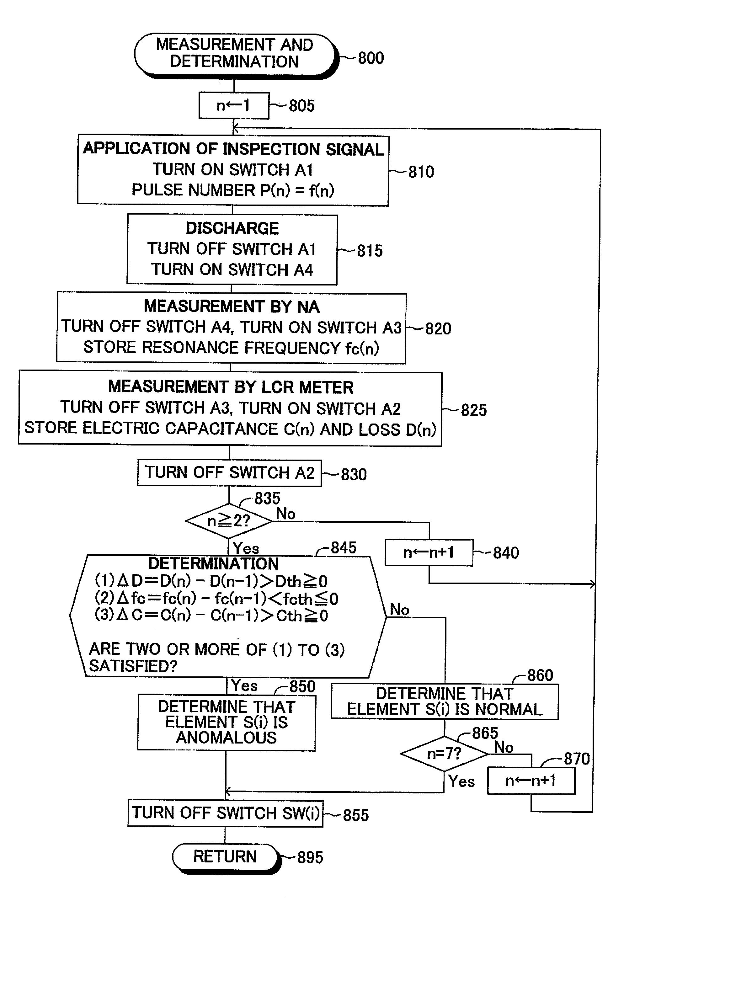
[0111] Next, a piezoelectric element inspection method (first inspection method) according to the present invention will be described. In this inspection method, the following steps are successively performed.

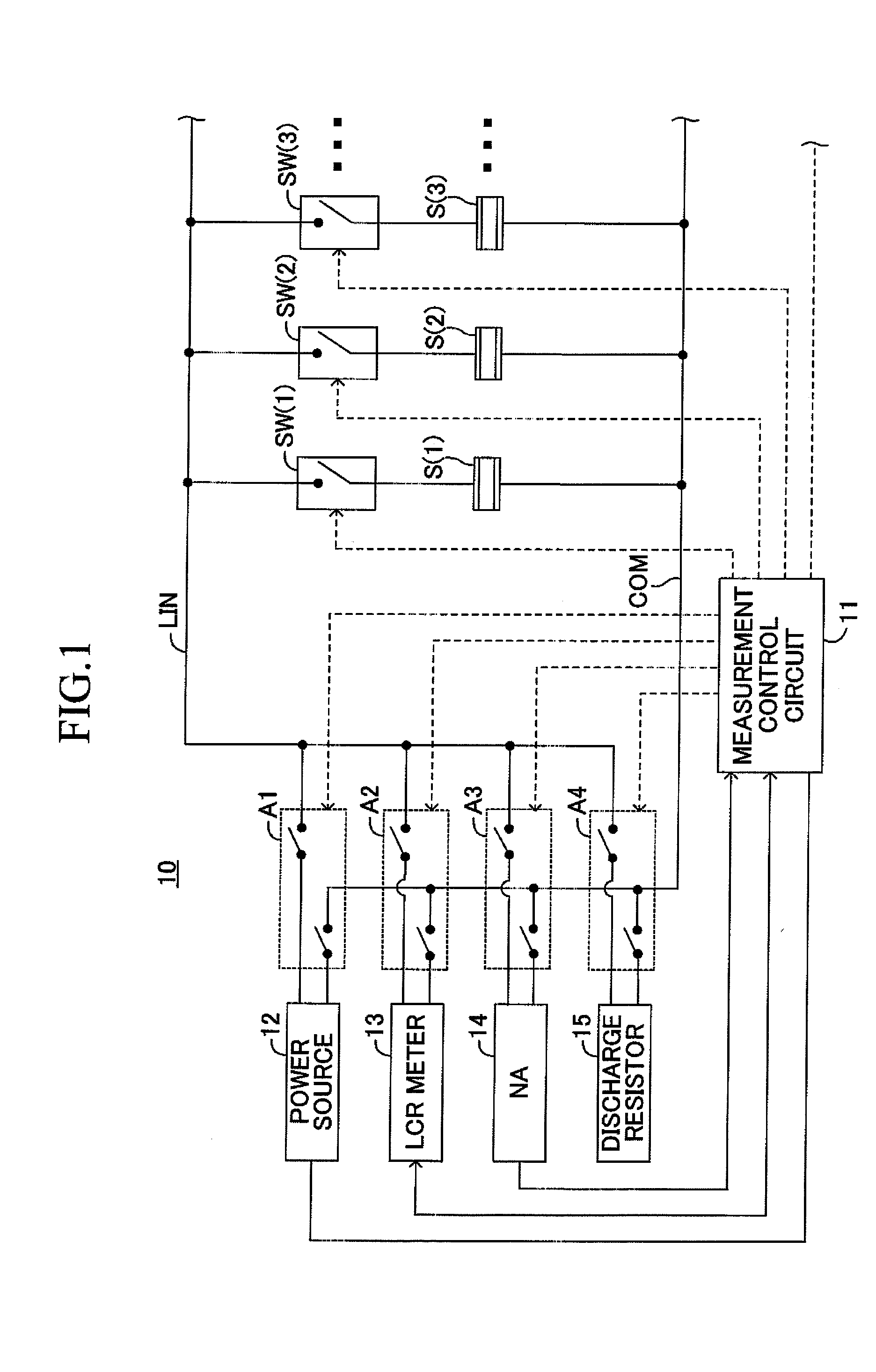
(1) Step 1: A predetermined first inspection signal Vp(1) is applied to a piezoelectric element (between the upper and lower electrodes of the piezoelectric element). The first inspection signal Vp(1) is generated by the power source 12.

[0112] The first inspection signal Vp(1) applied to the piezoelectric element in Step 1 has a first predetermined voltage waveform. As shown in a time period of t1 to t2 of FIG. 4, the first inspection signal Vp(1) is a voltage signal whose maximum voltage is Vpmax (in the present example, 300 V). The first inspection signal Vp(1) has a generally rectangular voltage waveform (envelope).

[0113] In actuality, as shown in FIG. 5, the first inspection signal Vp(1) is a voltage signal which has a waveform composed of a first number N1 of (a plurali...

second embodiment

[0171] Next, a piezoelectric element inspection method (second inspection method) according to the present invention will be described. In this inspection method, the following steps are successively performed.

(1) Step 1: A predetermined first inspection signal (inspection voltage Vp) Vp(1) is applied to a piezoelectric element. The first inspection signal Vp(1) is generated by the power source 12.

[0172] The first inspection signal Vp(1) applied to the piezoelectric element in Step 1 has a first predetermined voltage waveform. As shown in a time period of t1 to t2 of FIG. 9, the first predetermined voltage waveform is a voltage waveform whose maximum voltage Vpmax is V1 (in the present example, 100 V). The first inspection signal Vp(1) has a generally rectangular voltage waveform (envelope). In actuality, as shown in FIG. 10, the first inspection signal Vp(1) is a voltage signal which has a waveform composed of a plurality of successive trapezoidal waveforms (basic waveforms), in ...


PUM

PropertyMeasurementUnit
voltageaaaaaaaaaa
voltage Vpmaxaaaaaaaaaa

Abstract

A method for inspecting a piezoelectric element includes first-inspection-signal application step of applying to the piezoelectric element a first inspection signal Vp(1) having a first predetermined voltage waveform; first-characteristic-value measurement step of measuring, as a first characteristic value, an electrical characteristic value of the piezoelectric element after application of the first inspection signal; second-inspection-signal application step of applying to the piezoelectric element a second inspection signal Vp(2) having a second predetermined voltage waveform and an electrical power greater than that of the first inspection signal; second-characteristic-value measurement step of measuring, as a second characteristic value, the electrical characteristic value of the piezoelectric element after application of the second inspection signal; and anomaly determination step of determining whether or not the piezoelectric element is anomalous on the basis of a value corresponding to the difference between the measured second characteristic value and the measured first characteristic value.

Description

TECHNICAL FIELD [0001] The present invention relates to a method and an apparatus for inspection on whether or not a piezoelectric element is anomalous, and to a polarization method for polarizing a piezoelectric element. BACKGROUND ART [0002] A piezoelectric element (in the present specification, the term “piezoelectric element” encompasses “electrostrictive element”) is an element (device) which contracts or expands upon application of voltage thereto or an element which generates a voltage when it is contracted or expanded. Therefore, such a piezoelectric element is used in various apparatuses; for example, as a drive actuator of an ink injection device of a printer or the like, or as a sensor for measuring viscosity of fluid or the like. [0003] If an anomaly such as generation of a micro crack occurs in such a piezoelectric element, the piezoelectric element cannot provide a desired function. In view of this, in manufacture of piezoelectric elements, inspection is performed so a...

Claims


Application Information

Patent Timeline
Patent Type & Authority Applications(United States)
IPC IPC(8): H01L41/09G01N27/24B41J2/14B41J2/16H01L41/22H01L41/257
CPCB41J2/0451B41J2/04513B41J2/04541H01L41/257B41J2/14201G01R29/22B41J2/04581H10N30/045
Inventor OHNISHI, TAKAOYAMADA, TOMOHIRONEHAGI, TAKATOSHI
Owner NGK INSULATORS LTD
Why Eureka
Try Eureka