
Enhanced coverage hole detection in wireless networks

a wireless network and coverage hole technology, applied in the field of wireless networks, can solve the problems of poor audio, limit of earlier-generation systems, and impairment of the audio of end users

Active Publication Date: 2008-02-07
CISCO TECH INC
View PDF41 Cites 50 Cited by
  • Summary
  • Abstract
  • Description
  • Claims
  • Application Information

AI Technical Summary

Problems solved by technology

This inflection point has highlighted not only the limitations of earlier-generation systems, but also the changing role that WLAN technology now plays in people's work and lifestyles across the globe.
In Voice over Internet protocol (VoIP) systems and in particular VoIP over WLAN (VoWLAN) systems there are many points in the network that can cause audio impairments to the end users.
For example, gaps or “holes” in the radio coverage of a wireless access point are a primary cause of poor audio.
Unfortunately, existing coverage hole detection implementations suffer from false positive coverage hole alarms.
Algorithms in the central wireless controllers may provide some coverage hole detection functions, but such algorithms do not provide features that eliminate false positive reports for coverage hole alarms.

Method used


Image

  • Enhanced coverage hole detection in wireless networks
  • Enhanced coverage hole detection in wireless networks
  • Enhanced coverage hole detection in wireless networks

Examples


Embodiment Construction

A. Overview

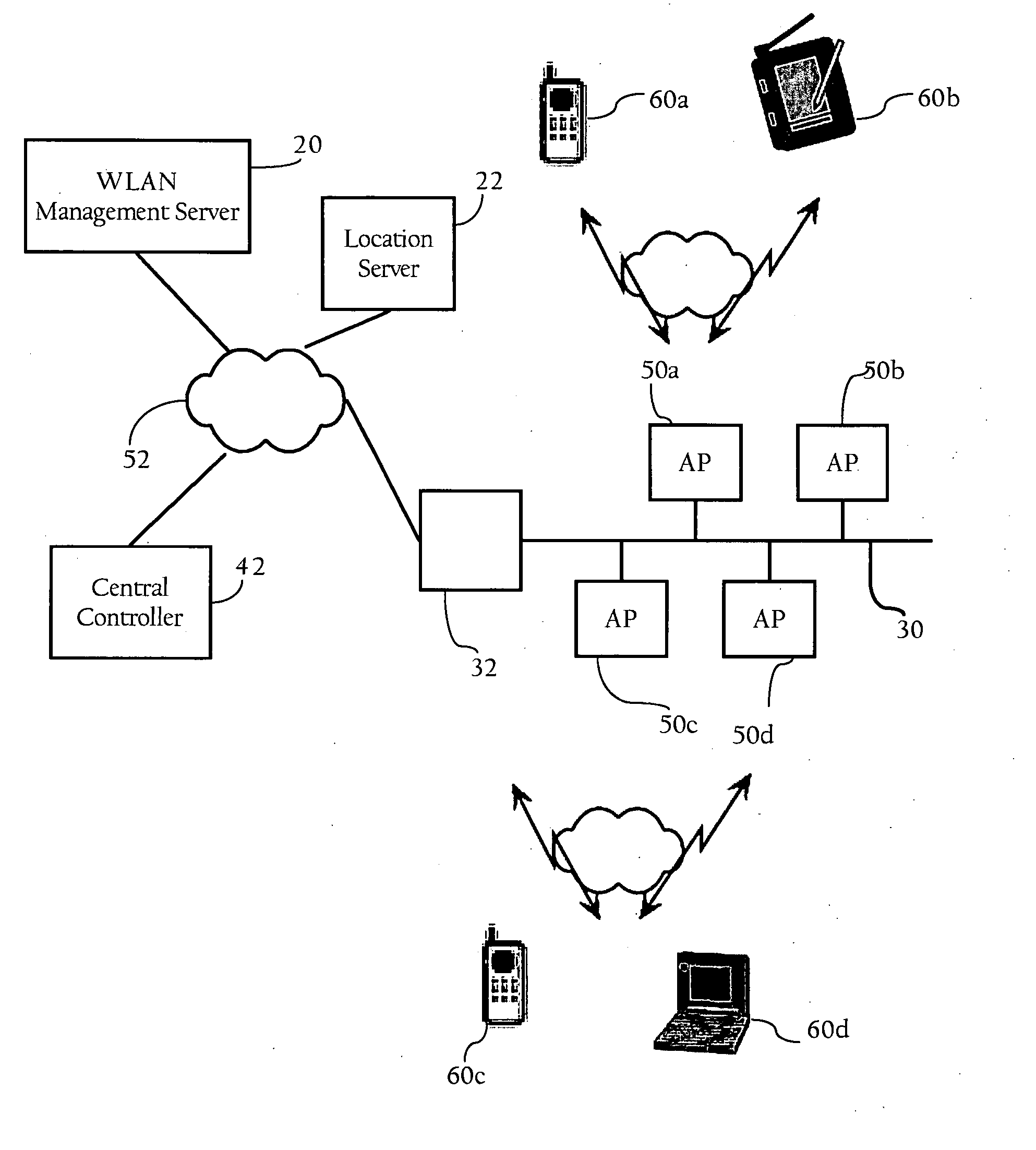
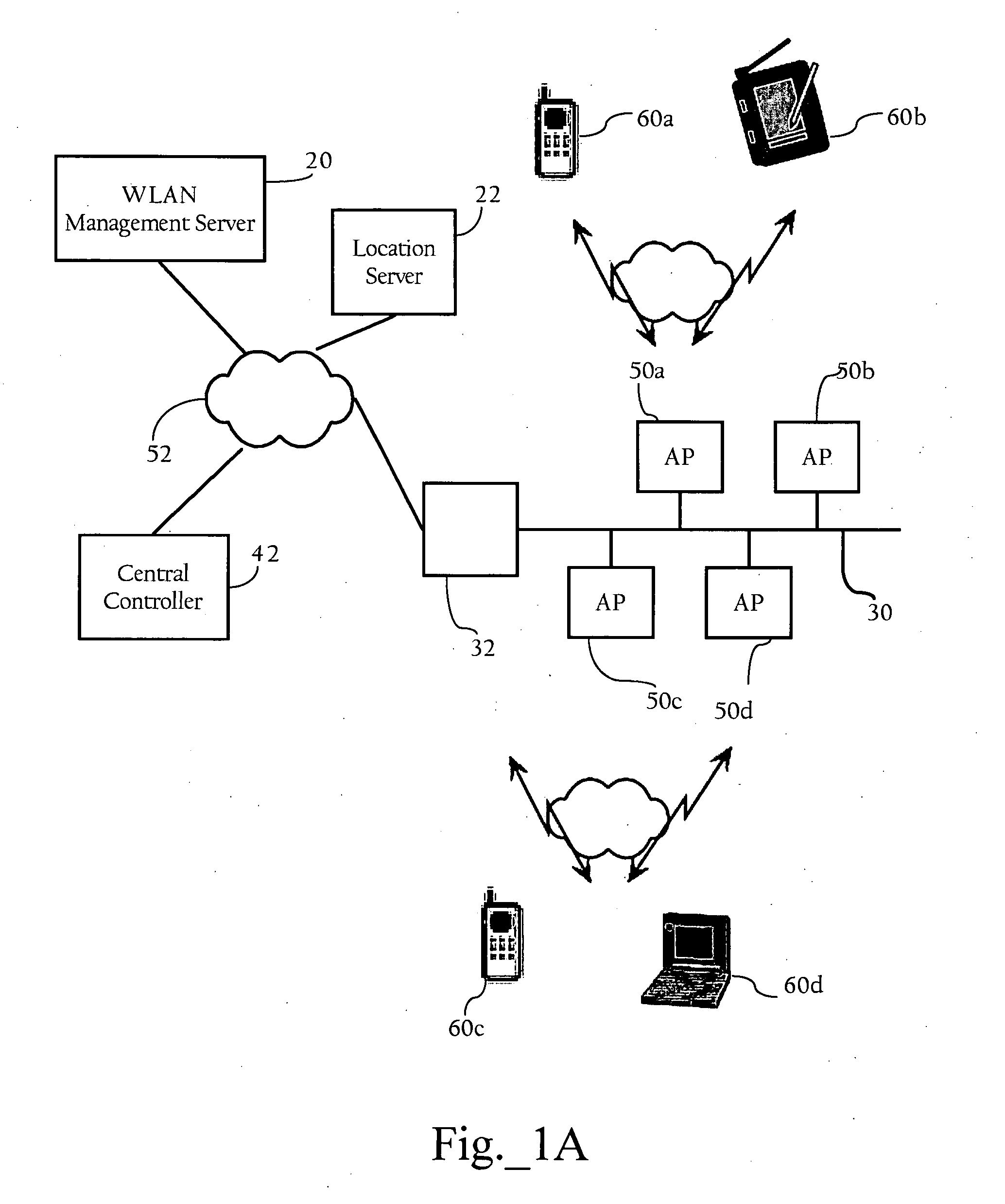
[0013]The present invention provides methods, apparatuses, and systems directed to identifying radio frequency (RF) coverage holes in wireless networks. According to one implementation of the present invention, the wireless network infrastructure analyzes received signal strength data to detect potential coverage holes associated with one or more wireless clients. In one implementation, the wireless network infrastructure processes receive signal strength indicator (RSSI) histograms that contain RSSI data corresponding to signals transmitted by wireless clients to identify potential coverage holes. A wireless client is considered to be in a “pre-alarm condition” if the amount of weak RSSI data associated with the wireless client rises above a threshold. A pre-alarm condition indicates a potential coverage hole that may be validated. As described in more detail below, the wireless network infrastructure validates potential coverage holes based on information obtained from ...


PUM


Abstract

Methods, apparatuses and systems directed to identifying coverage holes in wireless networks. According to one implementation of the present invention, the wireless network infrastructure analyzes signal strength data to detect potential coverage holes associated with one or more wireless clients and validates the potential coverage holes based on observed coverage data.

Description

FIELD OF THE INVENTION[0001]The present invention relates to wireless networks and, more particularly, to methods, apparatuses, and systems directed to identifying radio frequency coverage holes in wireless networks.BACKGROUND OF THE INVENTION[0002]Market adoption of wireless LAN (WLAN) technology has exploded, as users from a wide range of backgrounds and vertical industries have brought this technology into their homes, offices, and increasingly into the public air space. This inflection point has highlighted not only the limitations of earlier-generation systems, but also the changing role that WLAN technology now plays in people's work and lifestyles across the globe. Indeed, WLANs are rapidly changing from convenience networks to business-critical networks. Increasingly users are depending on WLANs to improve the timeliness and productivity of their communications and applications, and in doing so, require greater visibility, security, management, and performance from their net...

Claims


Application Information

Patent Timeline
Patent Type & Authority Applications(United States)
IPC IPC(8): H04Q7/20H04W24/00H04W24/08H04W84/12
CPCH04W24/00H04W84/12H04W24/08
Inventor STEPHENSON, DAVID SHELDONOLSON, TIMOTHY S.DOUGLAS, BRETTON LEE
Owner CISCO TECH INC
Learn More