Covering Device for Floor Coverings

a technology for floor coverings and covers, applied in the direction of decorative arts, structural elements, building components, etc., can solve the problems of reducing the stability of the profiled cover, virtually impossible to obtain a snug fit between the profiled cover and the compensating strip, and cannot always be taken for granted, so as to facilitate conventional coating and simple manufacturing conditions

Active Publication Date: 2008-02-14
NEUHOFER FRANZ JUN
View PDF26 Cites 23 Cited by
  • Summary
  • Abstract
  • Description
  • Claims
  • Application Information

AI Technical Summary

Benefits of technology

[0007]Although the form of the cross-section of the compensating strip can be designed in different ways, particularly simple manufacturing conditions are achieved when the compensating strip assumes the basic form of an angle section such that the leg with the retaining lug is adjacent to the underside of the covering flange of the profiled cover and the other forms an extension of the profiled cover extending downward. The leg of the angle section provided with the retaining lug therefore assists in transferring the load from the covering flange of the profiled cover to the leg of the angle section extending downward, which is supported on the lower floor surface.
[0008]For applications involving greater load requirements, the compensating strip can be provided with at least one additional supporting leg projecting downward from the leg with the retaining lug. It is also possible to connect the compensating strip to the fixture provided for accommodating the profiled cover by means of the supporting leg. To this end, the supporting leg of the compensating strip forms a coupling projection for connecting to the fixture for the profiled cover.
[0009]In order to join the compensating strip advantageously with the profiled cover, the compensating strip can be provided with a peripheral projection serving as a retaining lug in the area of the leg adjacent to the covering flange, with said projection engaging in a longitudinal groove serving as a retaining recess on the underside of the covering flange or on the side of the clamping web of the profiled cover facing the compensating strip, forming a pivot axis for the compensating strip. Consequently, to join the compensating strip to the profiled cover, the compensating strip with the peripheral projection only needs to be inserted into the corresponding retaining recess in the area of the covering flange or the clamping web in order to swivel the compensating strip around this peripheral projection serving as a pivot point against the underside of the covering flange until a retaining lug on the compensating strip engages in a corresponding longitudinal groove of the covering flange. Instead of a retaining lug on the leg, the leg of the compensating strip adjacent to the covering flange can also be provided with an adhesive surface on the side facing the covering flange by means of which the compensating strip is fastened to the underside of the covering flange. By anchoring the peripheral projection of the compensating strip in the corresponding retaining recess of the profiled cover, the torque resulting from the load of the profiled cover impinging on compensating strip can be reliably transferred, without having to worry about the compensating strip coming loose from the profiled cover.
[0010]The profiled cover and the compensating strip can be manufactured separately. However, particularly advantageous manufacturing conditions result when firstly an extruded profile is produced, the cross-section of which consists of the cross-sections of the profiled cover and at least one compensating strip, with said strip being connected to the subsequent profiled cover by means of a connecting land serving as a spacer, and then the compensating strip is separated from the profiled cover with a separating cut through the connecting land. The simultaneous manufacture of the profiled cover and at least one compensating strip does not only offer advantages with respect to the tooling costs, but also facilitates conventional coating on the visible surfaces of the profiled cover and the compensating strip, as in this case the profiled cover and the compensating strip can be coated together in one process. To this end, the connecting land between the profiled cover and the compensating strip forms a transition surface joining the visible surfaces of the profiled cover and the compensating strip and the transition surface is coated together with the visible surfaces of the profiled cover and the compensating strip, before the connecting land is severed. Simultaneously coating the profiled cover and the compensating strip means that the structure and visual appearance of the coating of the profiled cover and the compensating strip do not differ. The difference between the coatings of the profiled cover and compensating strips can at the most involve changes occurring at the kerfs, changes that are visually negligible owing to the width of the land, which is preferably restricted to the width of the kerf.

Problems solved by technology

However, such an adjustment for height differences with respect to the floor coverings being bridged requires the profiled covers to have the requisite flexural properties, which cannot always be taken for granted.
Furthermore, hollow cavities in the vicinity of the outer clamping webs of the covering flange result in a perceptible reduction in the stability of the profiled cover.
The disadvantage of this known covering device for floor coverings is primarily that the groove and the lug of the tongue-and-groove joint between the profiled cover and the compensating strip have to be machined from the timber material of these components with great effort and that it is virtually impossible to obtain a snug fit between the profiled cover and the compensating strip due to the unavoidable production tolerances used in manufacturing the profiled cover and the compensating strip.
Moreover, the profiled cover can only be used without a compensation strip as a cover for an expansion joint between two level floor coverings if the lug on the underside of the covering flange is removed beforehand.

Method used


Image

  • Covering Device for Floor Coverings
  • Covering Device for Floor Coverings
  • Covering Device for Floor Coverings

Examples


Embodiment Construction

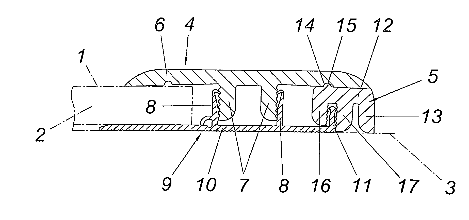
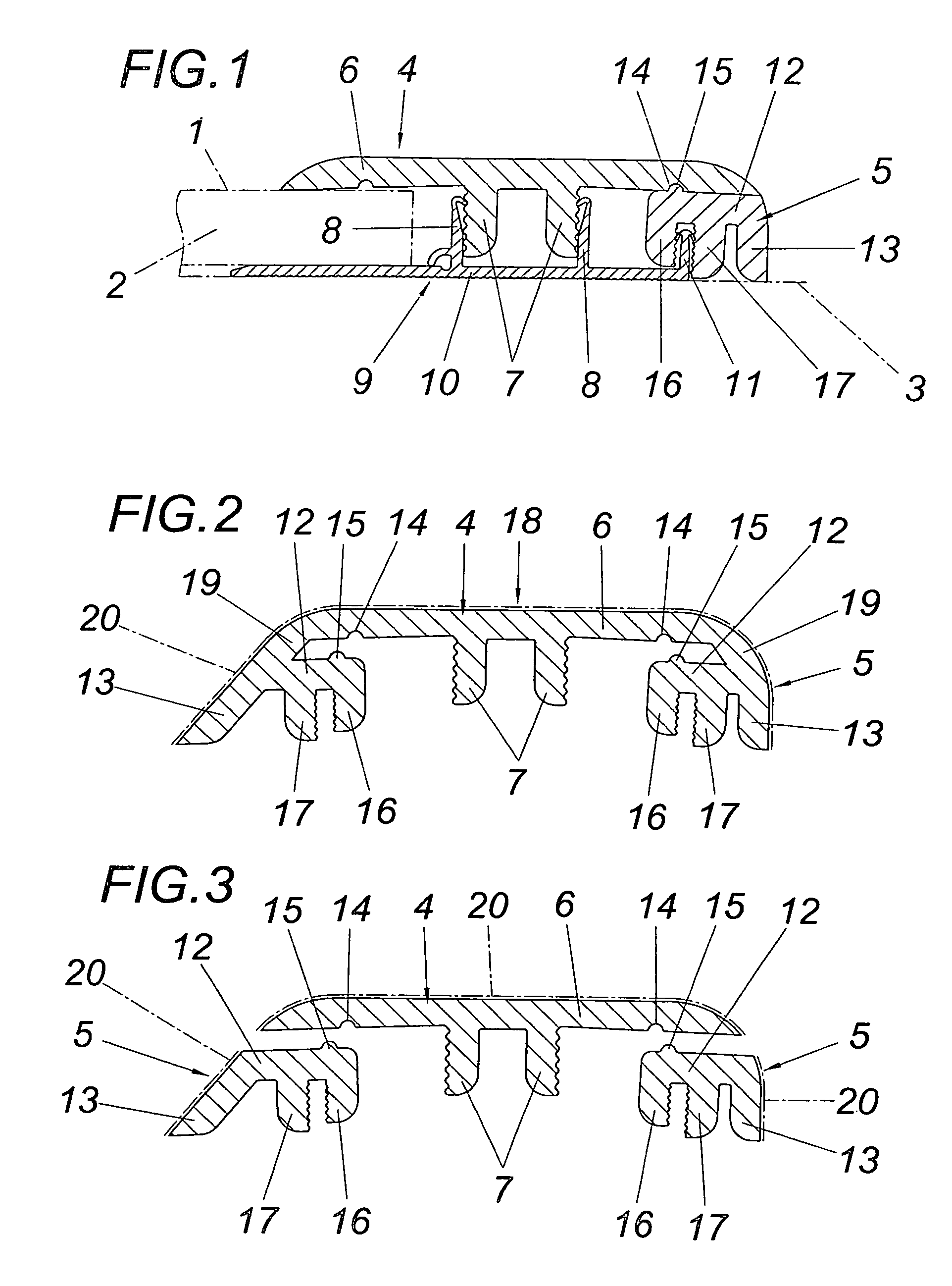
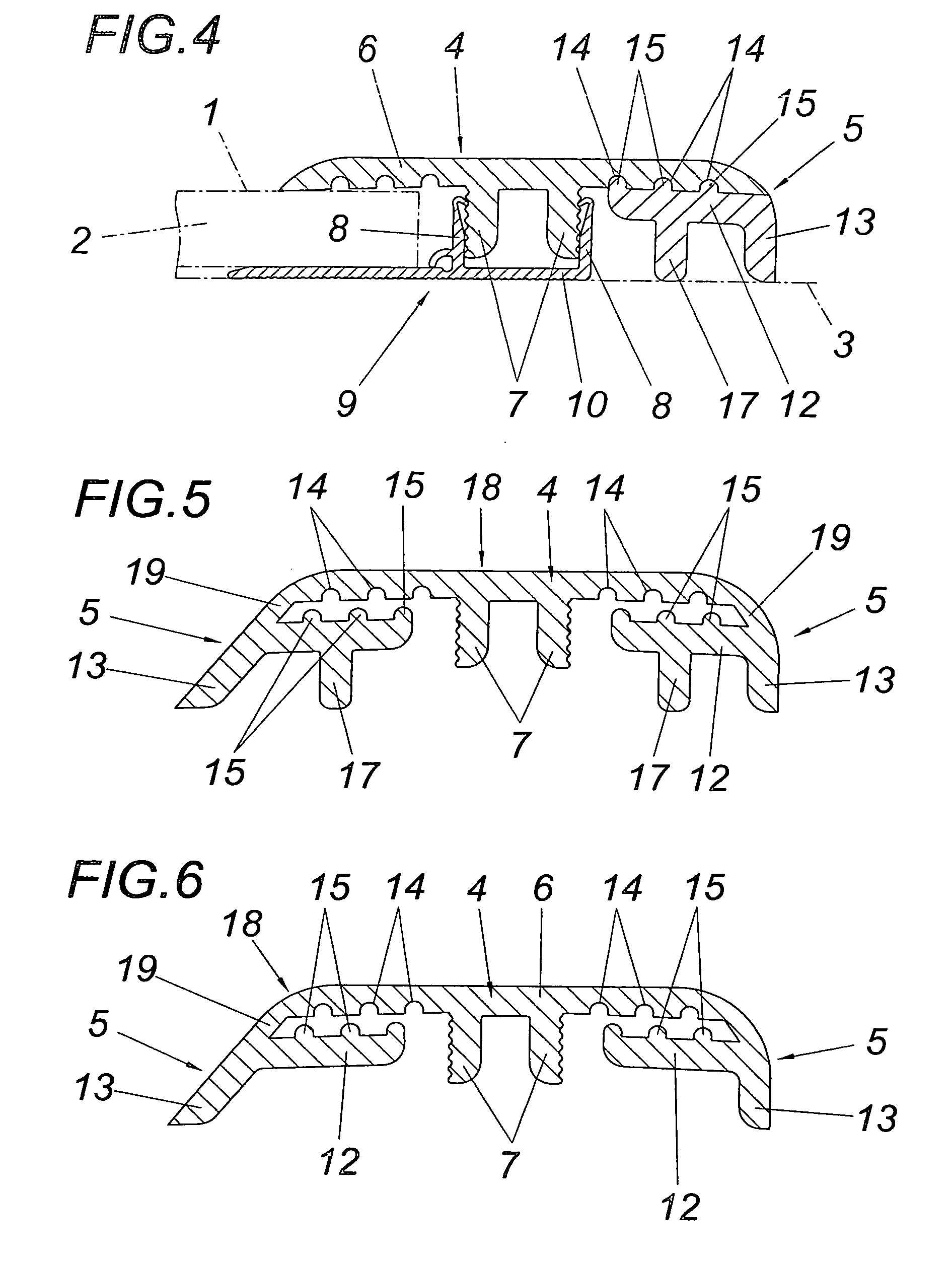
[0019]In accordance with the embodiment in FIG. 1, a difference in height between a floor surface 1, for instance a floor covering 2, and a floor surface 3 requires bridging, the latter surface in accordance with the embodiment being formed by the substrate for the floor covering 2. The floor surface 3 can of course also be formed by another floor covering. To bridge the difference in height between the floor surfaces 1 and 3, a covering device is used, comprising a profiled cover 4 and a compensating strip 5. The profiled cover 4 is provided with a covering flange 6 and two clamping webs 7 projecting from the covering flange 6, the clamping webs 7 being retained between two clamp-like retaining legs 8 of a fixture 9.

[0020]The fixture 9 is fastened to the substrate 3 by means of a floor mounting plate 10, with the floor mounting plate 10 being extended past the retaining legs 8 toward the compensating strip 5 and having an additional retaining leg 11 for the compensating strip 5. Th...


PUM


Abstract

A covering device for floor coverings (2) is described with a profiled cover (4) that is provided with one covering flange (6) and at least one clamping web (7) which protrudes downward from the covering flange (6), extends in the longitudinal direction of the profiled cover (4), and is used for fastening the profiled cover (4) in a fixture (9), with said device also comprising a compensating strip (5) that can be employed if desired, by being fastened to the profiled cover (4) by means of a form-fitting tongue and groove joint connecting to the underside of the covering flange (6). In order to provide advantageous manufacturing conditions it is proposed that the profiled cover (4), developed from an extruded profile, is provided with a tongue and groove joint formed by at least one longitudinal groove (14) for retaining a lug (15) of a compensating strip (5) also developed from an extruded profile.

Description

FIELD OF THE INVENTION [0001]The invention relates to a covering device for floor coverings with a profiled cover that is provided with one covering flange and at least one clamping web which protrudes downward from the covering flange, extends in the longitudinal direction of the profiled cover, and is used for fastening the profiled cover in a fixture. The invention also comprises a compensating strip that if required can be fastened to the underside of the covering flange my means of a form-fitting tongue and groove joint.DESCRIPTION OF THE PRIOR ART [0002]A known method for bridging steps or joints in floor coverings is disclosed in WO 99 / 01628 A1, wherein profiled covers for steps and joints are invisibly attached by means of fixtures. For this purpose, the fixtures consists of a profiled section with a flat horizontal fastening element on the floor side. Extending upward from this flat horizontal element are vertical fastening legs, between which the downwardly protruding clam...

Claims


Application Information

Patent Timeline
Patent Type & Authority Applications(United States)
IPC IPC(8): E04F19/06
CPCE04F19/061E04F19/065E04F19/062
Inventor NEUHOFER, FRANZ JUN.
Owner NEUHOFER FRANZ JUN
Why Eureka
Try Eureka