Metal photomask box

Inactive Publication Date: 2008-02-14
GUDENG PRECISION IND CO LTD
View PDF10 Cites 7 Cited by
  • Summary
  • Abstract
  • Description
  • Claims
  • Application Information

AI Technical Summary

Benefits of technology

[0004]A main objective of the present invention is to provide a structure of the metal photomask box that uses the metal photomask box to prevent from the damages caused by ESD and EMI to the photomask.
[0005]Another objective of the present invention is to provide a structure of the metal photomask box with airtight effect that isolates the photomask in the metal photomask box from air and prevents from the fogging effect that can reduce the duration of the photomask.
[0006]Still another objective of the present invention is to provide a structure of the metal photomask box with filling function that not only reduces the fogging effect but also increases the storing time of the photomask.
[0007]And still another objective of the present invention is to provide a structure of the metal photomask box that can detect vibration and thus can monitor the storing condition of the metal photomask box by using a vibration detecting device.
[0008]The present invention further provides another objective, which is to provide a cover member of a metal photomask box provided with a RFID that can rapidly identify the storing position of the metal photomask box.
[0014]By using the design disclosed by the present invention, not only can the photomask be smoothly and easily led into the photomask box and effectively locked, but ESD and EMI can also be prevented and thus extend the duration of the photomask. Moreover, the metal photomask box with air filling function provided by the present invention also offers an airtight space to protect the photomask and prevent from fogging effect on the photomask.

Problems solved by technology

As Fabs. move toward more advanced processes, in addition to ESD, EMI in Fabs. will also damage the photomasks on account of the development of processes, especially when the photomasks are in condition of storage and the changes in the surroundings cannot be expected.

Method used


Image

  • Metal photomask box
  • Metal photomask box
  • Metal photomask box

Examples


Embodiment Construction

[0021]The present invention discloses a structure for metal photomask boxes. Some detailed procedures for fabricating or processing the photomask or photomask box applied in the present invention are accomplished by using current techniques and will not be completely described in the following description. And the drawings in the following are not drawn according to actual sizes, the function of which is only to illustrate features related to the present invention.

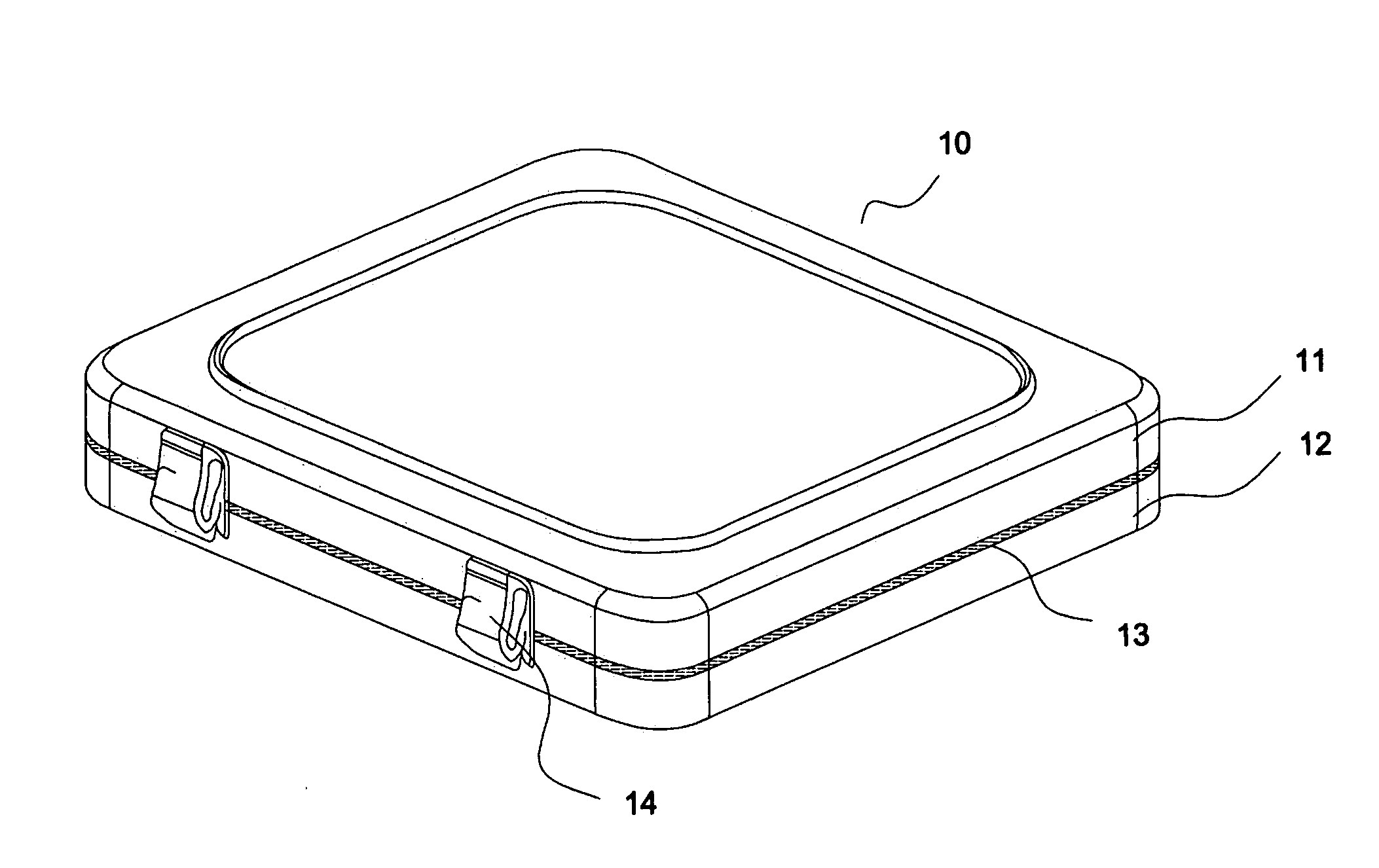
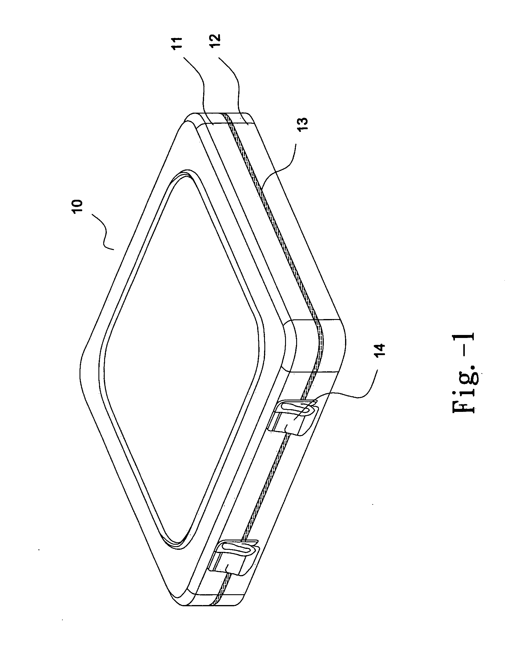
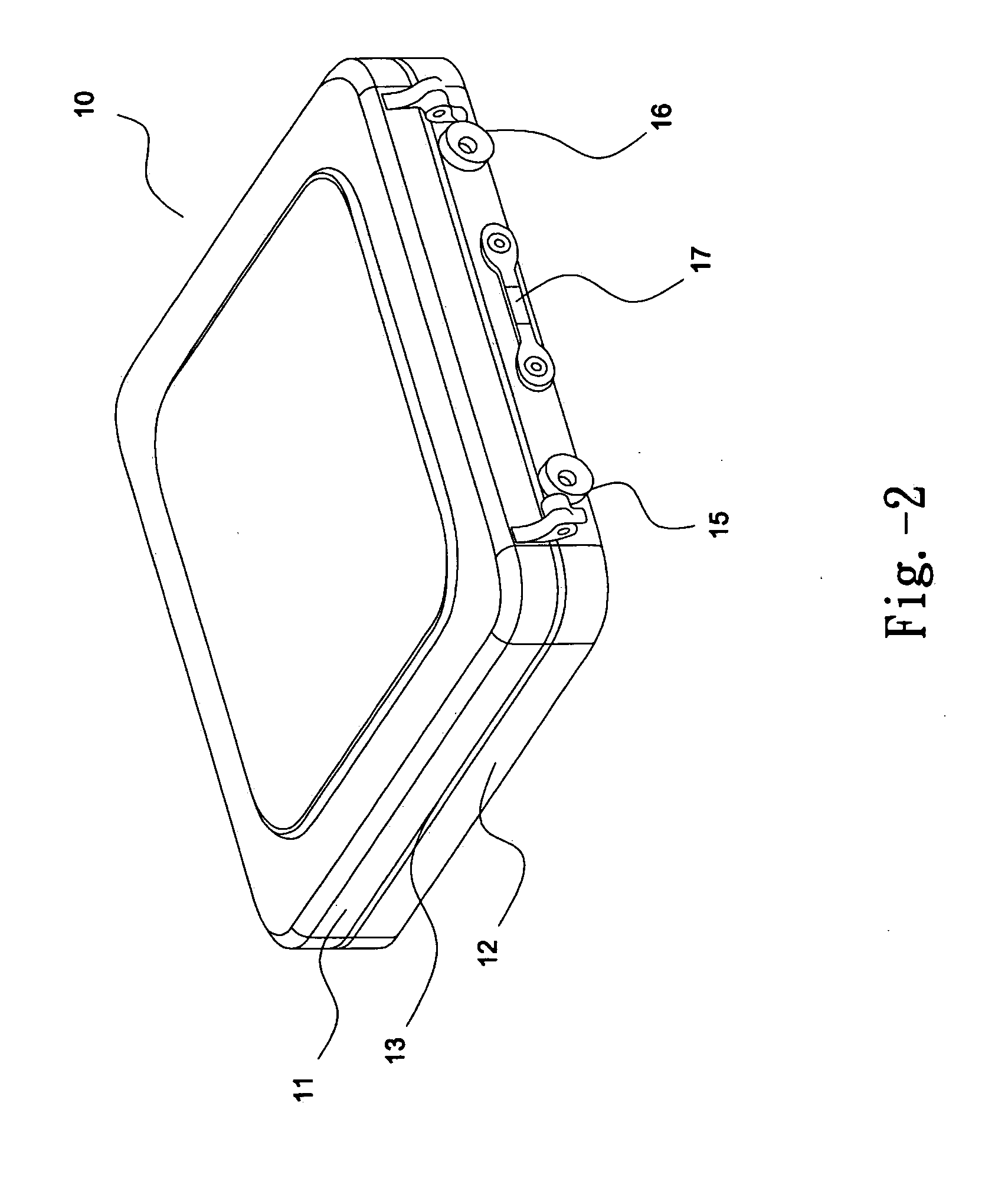
[0022]First, referring to FIG. 1 and FIG. 2, which are diagrams of a metal photomask box according to the present invention. Metal photomask box 10 according to the present invention comprises a metal upper cover member 11, a metal lower cover member 12, a ring-shaped airtight washer 13 disposed between the metal upper cover member 11 and the metal lower cover member 12, and a latch piece 14. Therefore, the metal photomask box 10 can be covered by the metal upper cover member 11, the metal lower cover member 12, and the ri...


PUM


Abstract

The present invention relates to a metal photomask box structure, which is composed of an upper cover member, a lower cover member, and a ring-shaped airtight washer positioned between the upper metal cover member and the lower metal cover member. At least a movable connecting mechanism is disposed on one side of the metal photomask box to connect the upper metal cover member and the lower metal cover member. And at least a latch piece is disposed on an opposite side of the movable connecting mechanism to latch the upper metal cover member and the lower metal cover member.

Description

FIELD OF THE INVENTION[0001]The present invention relates to a photomask box, and more particularly, to a structure of the metal photomask box.DESCRIPTION OF THE PRIOR ART[0002]Currently, advanced Foundries or Fabs. have stepped toward 90 nm in the process of manufacturing chips. Therefore, the most urgent thing to do is to reduce the line width of photomasks that are used to carry out the exposing process. Since photomasks require high cost, the duration of photomasks has to be extended in order to reduce the manufacturing cost. There have already been many techniques focusing on the retaining piece or the locking piece in photomask boxes, used in the hope for effective damage reduction caused in the process of transporting or storing. In addition, there are also some techniques that add ESD devices in photomask boxes to prevent the photomasks from being damaged by static electricity.[0003]As Fabs. move toward more advanced processes, in addition to ESD, EMI in Fabs. will also dama...

Claims


Application Information

Patent Timeline
IPC IPC(8): B65D85/48
CPCH01L21/67288H01L21/67294H01L21/67353H01L21/67359H01L21/67396H01L21/67373H01L21/67383H01L21/67393H01L21/67369
Inventor CHIU, MING-LUNGWANG, CHIEN FENG
Owner GUDENG PRECISION IND CO LTD
Why Eureka
Try Eureka