Aircraft Door Arrangement With an Aircraft Door That Swings By 180

a technology of aircraft doors and hinges, which is applied in the direction of door/window fittings, wing accessories, transportation and packaging, etc., can solve the problems of large play of translational articulated elements, and complex kinematics of the door joint mechanism, so as to achieve a high degree of precision and low bearing clearance. , the effect of precise fi

Active Publication Date: 2008-02-14
AIRBUS HELICOPTERS DEUT GMBH
View PDF10 Cites 11 Cited by
  • Summary
  • Abstract
  • Description
  • Claims
  • Application Information

AI Technical Summary

Benefits of technology

[0014]The door arrangements according to the invention with their seven-joint linkage make it possible to always guide the door accurately over a very large pivoting angle range along a precisely defined path of motion when the door is opened or closed. This high level of precision is ensured particularly since the seven-joint linkage does not have any translational linkage elements or linkage elements that are mounted in a translational manner and the seven joints are designed exclusively as rotational joints with which a very precise fit and very little bearing clearance can easily be achieved. The precisely defined path of motion of the door is determined by the kinematics of the seven-joint linkage. The seven-joint linkage also ensures that the position of all of the involved linkage elements is always unambiguously defined while the door is being moved.
[0015]Moreover, it has been found that the seven-joint linkage, in spite of its joints being configured exclusively as rotational joints, is capable of effectuating an opening and closing procedure in which the door—starting from the closed position in which considerable portions of the door are situated inside the door frame—can be moved out of the door frame and partially or completely around an edge of the door frame into an open position that is essentially outside of the fuselage, without colliding with the fuselage structure in this process. Increased reliability and precision can also be achieved in this context.
[0016]Moreover, with the seven-joint linkage of the door arrangement according to the invention, the position of the door relative to the door frame can be determined unambiguously and with a very precise fit when the door is in the closed position. As a result, the door can be sealed more easily and more precisely against the internal cabin pressure of the fuselage and more favorable sealing conditions can be attained. Finally, when the door is in the open position, the door arrangement according to the invention with its seven-joint linkage allows a very favorable transmission and application of the loads emanating from the opened door towards and into the fuselage structure.

Problems solved by technology

This calls for very complex kinematics of the door joint mechanism since the door has to be prevented from colliding with parts of the fuselage structure along the path of motion of the door.
This large pivoting angle range, in conjunction with the above-mentioned necessary properties of the door and of the adjacent fuselage structure, require a quite complex door joint mechanism and this is another reason for the complexity of the kinematics of the door.
With such conventional door arrangements, however, it has been found that the translational articulated elements exhibit quite a lot of play and that they cannot always guide the door precisely over the large pivoting range.
Moreover, due to the translational articulated elements, the position of all of the articulated elements involved when the door is being opened or closed is not unambiguously defined.
Furthermore, when a door joint mechanism with translational articulated elements is used, the position of the door relative to the door frame cannot be defined precisely enough which, in turn, means that the sealing of the door against internal pressure of the cabin can only be realized with a great deal of effort and the sealing conditions are unfavorable.
Moreover, when the door is in the open position, the transmission and application of the loads emanating from the opened door towards and into the fuselage structure are unfavorable.

Method used


Image

  • Aircraft Door Arrangement With an Aircraft Door That Swings By 180
  • Aircraft Door Arrangement With an Aircraft Door That Swings By 180
  • Aircraft Door Arrangement With an Aircraft Door That Swings By 180

Examples


Embodiment Construction

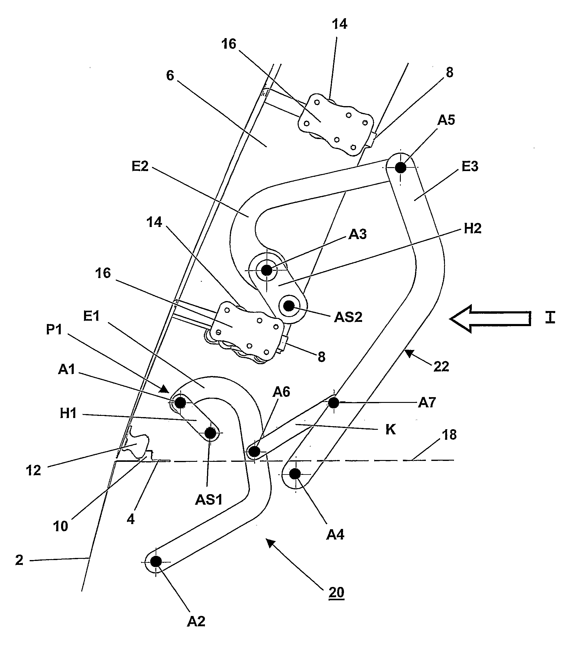
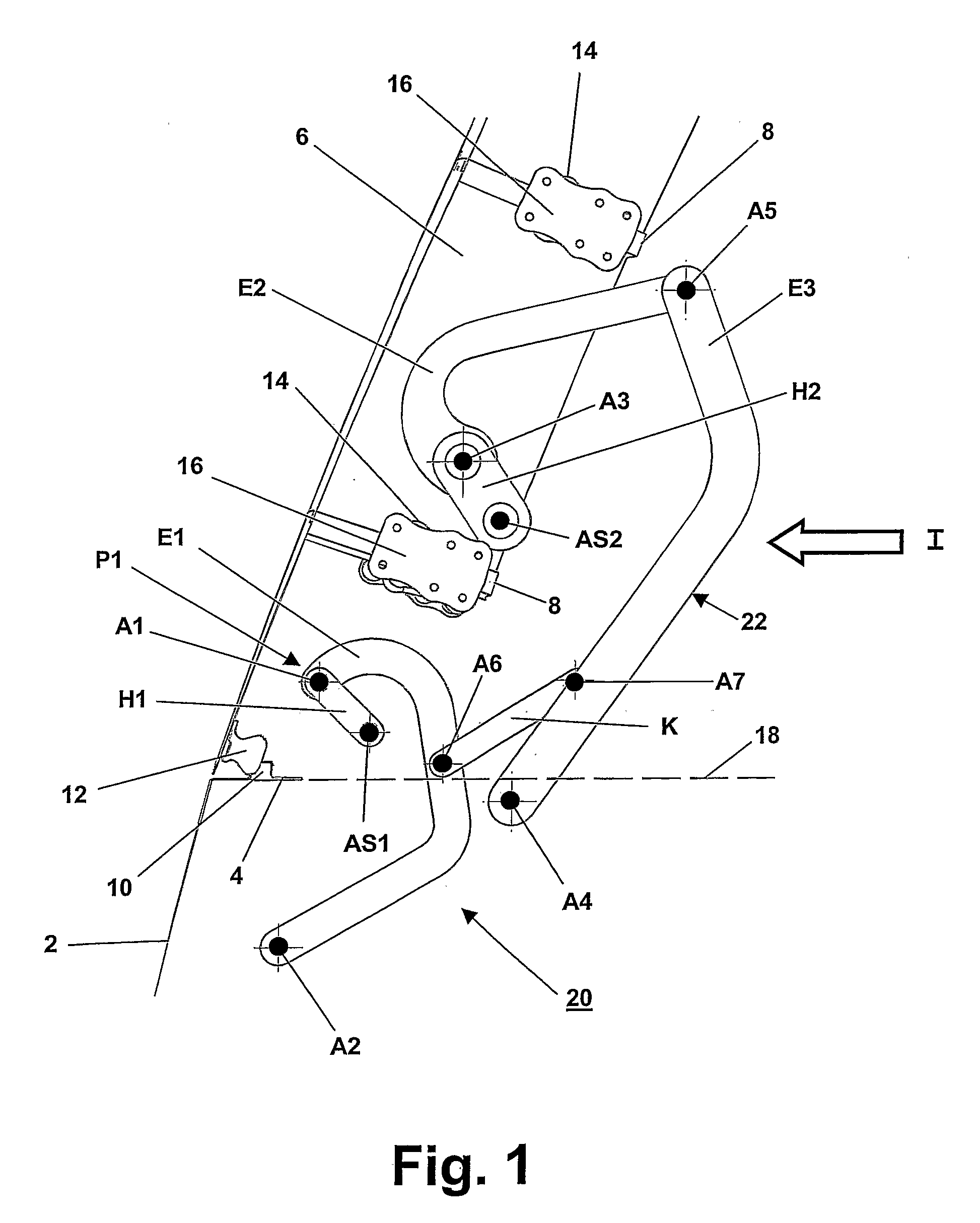
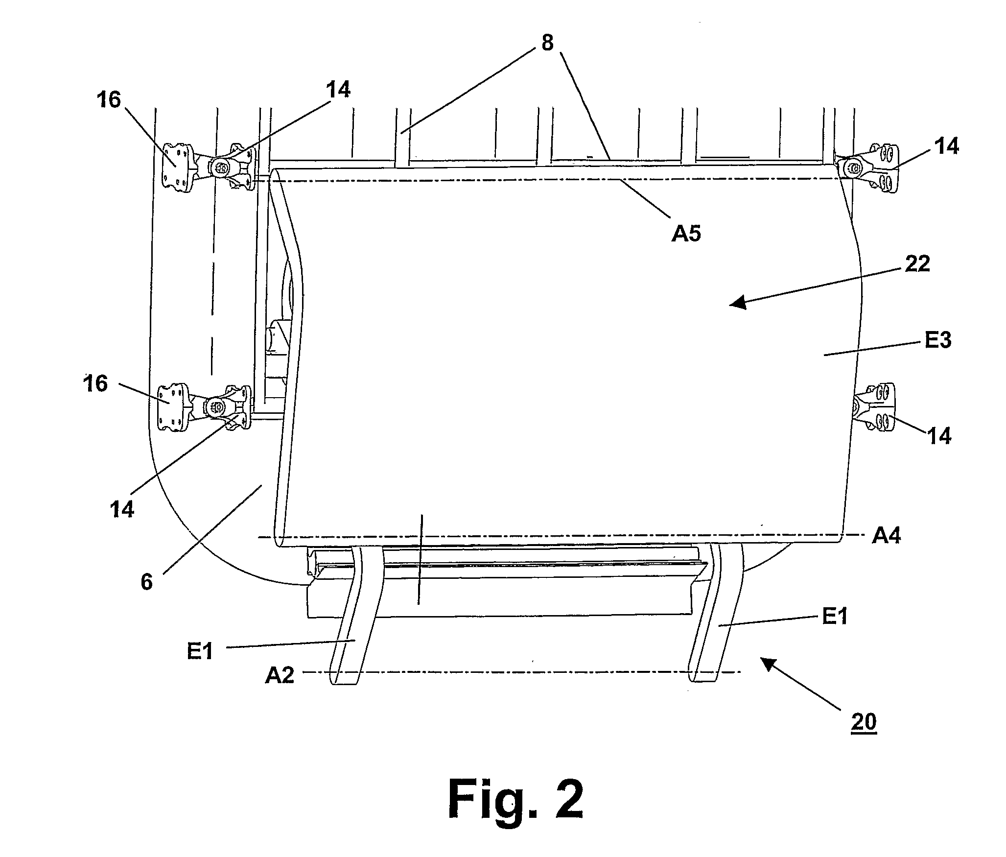
[0027]FIG. 1 shows a schematic cross-sectional view of a lateral area of an aircraft fuselage 2 belonging to a passenger aircraft according to the invention and provided with a pressurized cabin, said aircraft being equipped with a door arrangement according to the invention. The fuselage 2 has a fuselage structure that includes a door frame 4 surrounding a door opening located in the fuselage 2. A door 6, which is configured in this embodiment as an emergency-exit door and which can be opened and closed, has a door structure 8 and is arranged inside the door frame 4. This door 6 is the type of door that, starting from an open position, can be moved into a closed position and locked in the closed position by means of a door locking mechanism and said door has to be lowered to be locked and then raised again in order to be unlocked. In order to raise and lower the door 6, the door arrangement is provided with a lifting device that will be described in greater detail below and by mean...


PUM


Abstract

A door arrangement for an aircraft that has a fuselage with a fuselage structure includes a door to be arranged inside a door frame of the fuselage structure and a door joint mechanism attached to the door of the door frame and to the fuselage structure. The door joint mechanism has a seven-joint linkage provided with first to seventh joints by means of which the door, guided exclusively in a rotationally articulated manner, is moveable over a predefined pivoting angle range from a closed position inside the door frame to an open position outside of the door frame and fuselage, and back again. In addition, an aircraft, especially a fixed-wing aircraft, encompassing at least one aircraft door arrangement is provided.

Description

FIELD OF THE INVENTION[0001]The present invention relates to a door arrangement for an aircraft that has a fuselage with a fuselage structure that includes a door frame surrounding a door opening, said door arrangement having a door that is to be arranged inside the door frame as well as having a door joint mechanism that is attached to the door and to the fuselage structure. Moreover, the invention relates to an aircraft with such a door arrangement.DESCRIPTION OF RELATED ART[0002]Door arrangements are known for aircraft having a fuselage with a fuselage structure that includes a door frame surrounding the door opening. The door arrangement has a door that is to be arranged inside the door frame and a door joint mechanism that is attached to the door and to the fuselage structure. For aerodynamic reasons, the outer contour of the door has to lie flush with the outer contour of the fuselage structure adjacent to the door frame. This aspect as well as the considerable thickness of th...

Claims


Application Information

Patent Timeline
Patent Type & Authority Applications(United States)
IPC IPC(8): B64C1/14
CPCB64C1/1407
Inventor OBST, STEFFEN
Owner AIRBUS HELICOPTERS DEUT GMBH
Why Eureka
Try Eureka