Eureka AIR delivers breakthrough ideas for toughest innovation challenges, trusted by R&D personnel around the world.

Aerodynamic fork mast structure

Active Publication Date: 2008-02-14
CERVELO USA INC
View PDF10 Cites 32 Cited by
  • Summary
  • Abstract
  • Description
  • Claims
  • Application Information

AI Technical Summary

Benefits of technology

[0007] In the field of bicycle design and racing, aerodynamics plays an important role. Bicycles are now being designed to further reduce aerodynamic drag.
[0013] Where the mounting device is an external mounting bracket it can be moved up and down relative to the mast and fixed to the mast at any one of a plurality of desired positions along the mast thus providing the height of the handlebar to be adjustable by sliding the mounting bracket longitudinally along the mast. Where the mounting device is an internal plug to be received within an internal mast bore at the upper end of the mast, the mast can be cut at a desired height. Preferably the mast is angled upwardly and forwardly such that the upward sliding of the mounting bracket causes the handlebar member to move forwardly and the downward sliding of the mounting bracket causes the handlebar system to move rearwardly. This adjustability allows the mast to accommodate differently sized riders.
[0017] The mast may also be a separate structure that is removably secured to the remainder of the front fork as by receiving a tubular extension of a fork head within an internal socket in the mast. This is of particular advantage when using the mast in combination with a “conventional” fork, which is affixed to the frame via a cylindrical steerer tube.
[0022] In a further aspect, the top of the fork mast may be cut to a suitable height to reduce the aerodynamic drag on the mast. The mast may also be cut for adjustability of the handlebars on the mast. The handlebars may have instead of a mounting bracket, a tenon that extends downwardly from a centre portion of the handlebar. The tenon is shaped to fit into an interior bore of the mast. The tenon and bore arrangement allows the handlebar to attach to the mast. Since the top of the mast can be cut, the height of the handlebars can be adjusted to suit the rider.

Problems solved by technology

Known prior art fork mast structures have not been designed to reduce aerodynamic drag on the bicycle.
While handlebar systems have been separately designed for aerodynamic results previously known devices have not provided a system wherein a fork mast structure, which can be connected to the handlebar system, is aerodynamic and provides handlebar adjustability, reduced weight, and improved structural integrity.
However, none of the previous prior art disclosures have taught a system wherein the fork mast structure is designed to have an aerodynamic shape and permits easy attachment to a handlebar system.

Method used


Image

  • Aerodynamic fork mast structure
  • Aerodynamic fork mast structure
  • Aerodynamic fork mast structure

Examples


Embodiment Construction

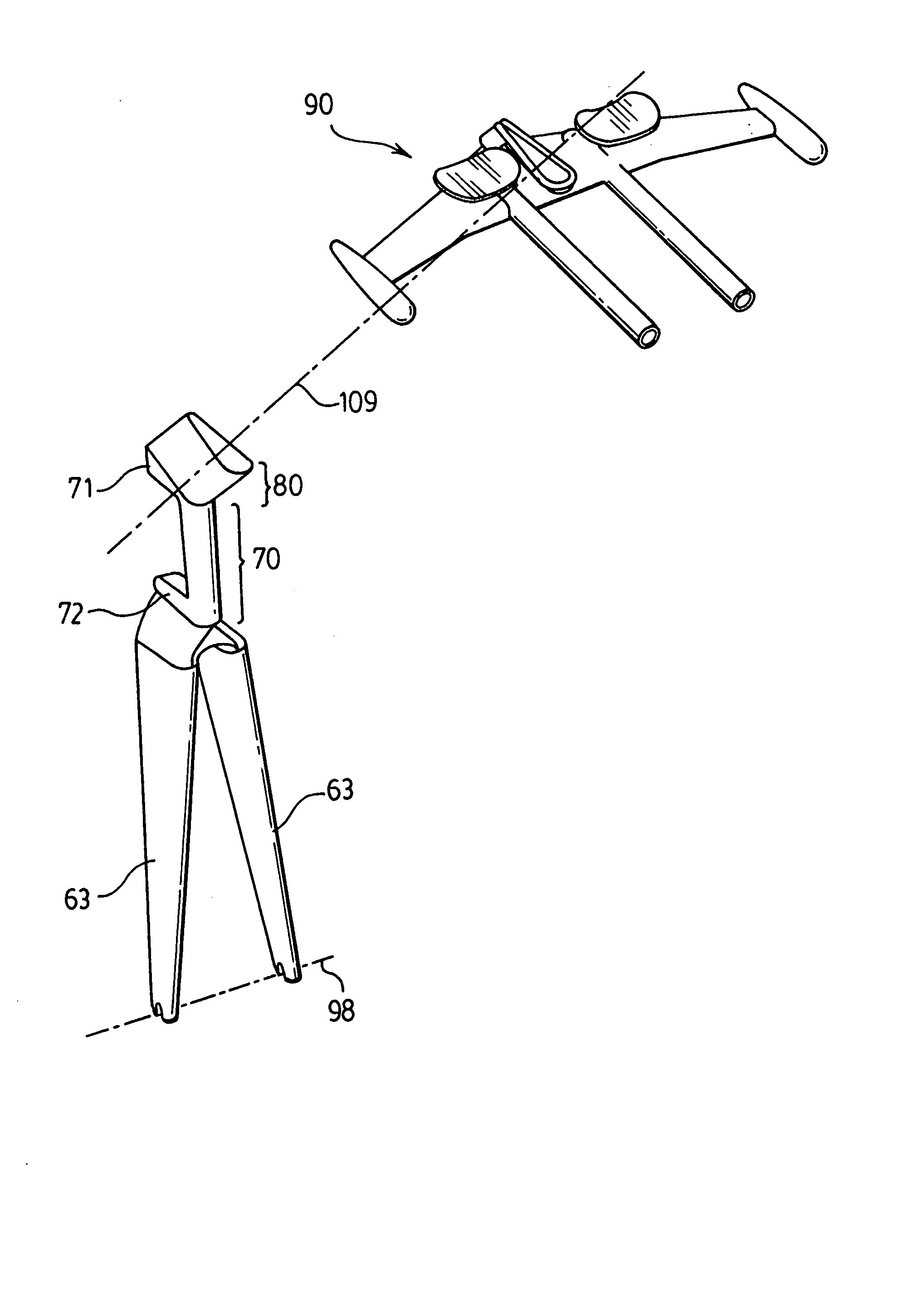
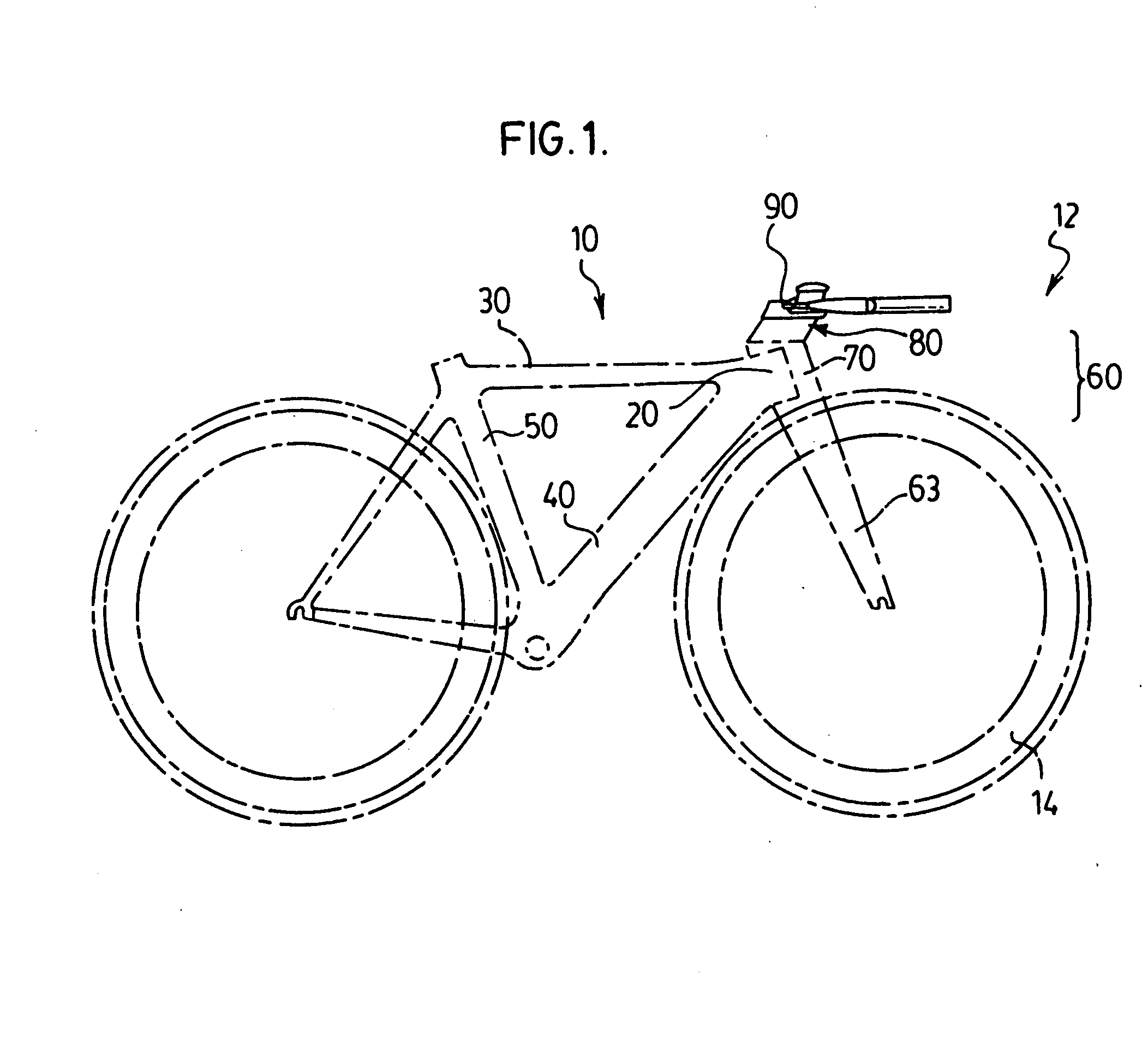
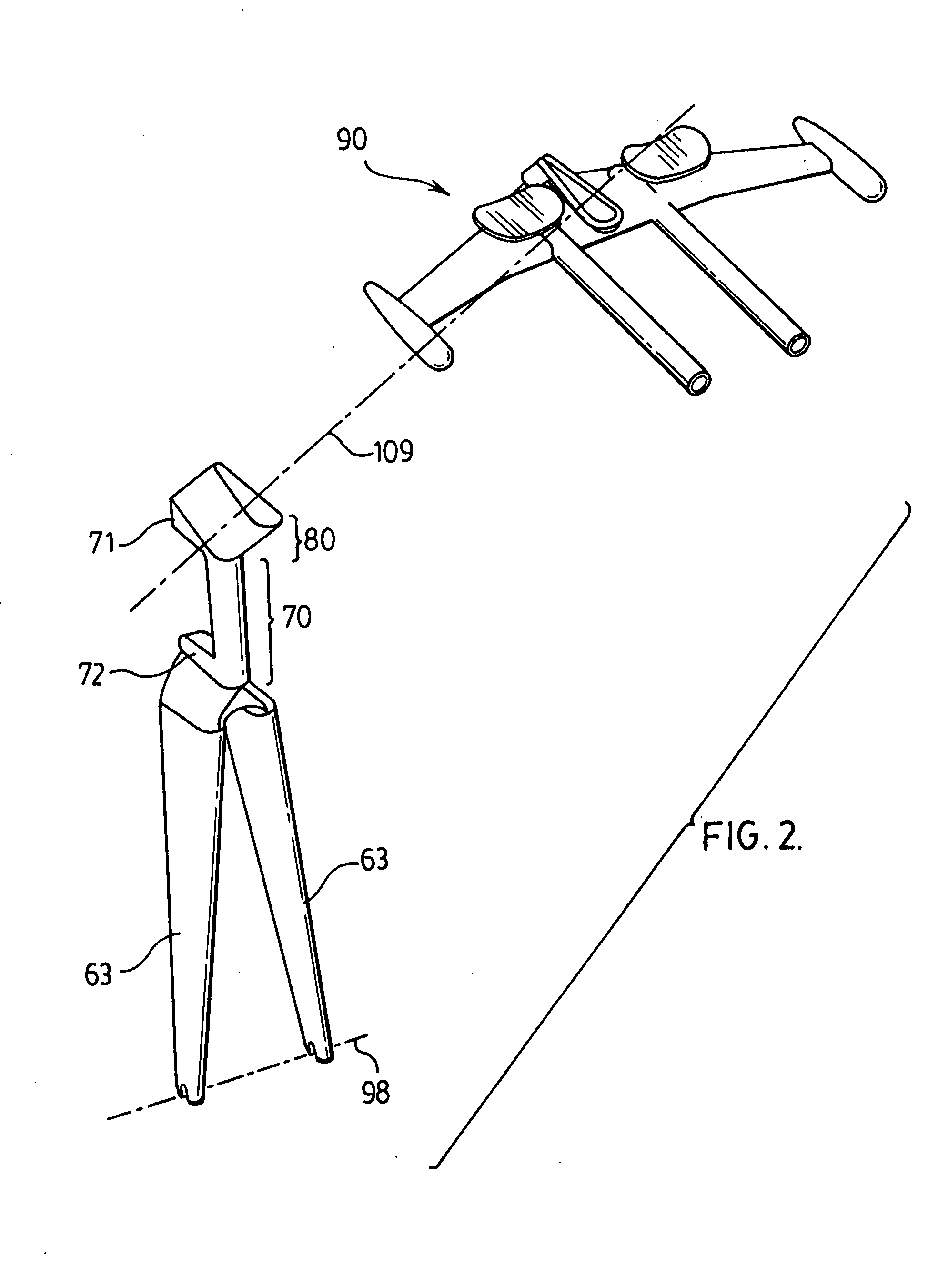
[0042] Preferred embodiments of the invention and its advantages can be understood by referring to the present drawings. Through all of the drawings the same reference numbers are used to refer to similar elements.

[0043]FIG. 1 shows a bicycle including a frame 10 having a front fork 60 with an integral mast 80 supporting the handlebars assembly 90.

[0044] The frame 10 comprising a head tube 20, a top tube 30, a down tube 40 and a seat tube 50. The bicycle, when in normal use, moves in a forward direction where the head tube 20 and down tube 40 are forward of the seat tube 50. The top tube extends generally in a forward direction. Each of the top tube 30, head tube 20, down tube 40, and seat tube 50 is a tubular member extending about their own longitudinal axis. The longitudinal axis of each of the tubular members lies in a flat longitudinal central plane running through a longitudinal axis centrally of each of the head tube 20, top tube 30, down tube 40 and seat tube 50.

[0045] Th...


PUM


Abstract

A front fork for a bicycle having an upwardly extending mast of an aerodynamic teardrop shape to which a handlebar may readily be attached.

Description

RELATED APPLICATION [0001] This application is related to and claims the benefit as under 35 U.S.C. 119 of U.S. Provisional Patent Application No. 60 / 836683 filed Aug. 10, 2006FIELD OF THE INVENTION [0002] The present invention relates to an aerodynamic front fork mast structure for use in a bicycle. BACKGROUND OF THE INVENTION [0003] Known prior art fork mast structures have not been designed to reduce aerodynamic drag on the bicycle. While handlebar systems have been separately designed for aerodynamic results previously known devices have not provided a system wherein a fork mast structure, which can be connected to the handlebar system, is aerodynamic and provides handlebar adjustability, reduced weight, and improved structural integrity. [0004] In the past, handlebar systems have been attached to fork mast structures in a variety of different ways. However, none of the previous prior art disclosures have taught a system wherein the fork mast structure is designed to have an aer...

Claims


Application Information

Patent Timeline
IPC IPC(8): B62K19/30
CPCB62K19/04B62K21/12B62K19/32B62K21/02
Inventor VROOMEN, GERARDWHITE, PHILIP
Owner CERVELO USA INC
Why Eureka
Eureka Blog
Learn More