
Manipulation desk for printing machines

Inactive Publication Date: 2008-02-14
MITSUBISHI HEAVY IND PRINTING & PACKAGING MACHINERY
View PDF7 Cites 3 Cited by
  • Summary
  • Abstract
  • Description
  • Claims
  • Application Information

AI Technical Summary

Benefits of technology

[0010]The present invention has been made in view of the circumstances described above. Accordingly, it is the primary object of the present invention to provide a manipulation desk for printing machines that is capable of easily recognizing the position of a target ink adjustment switch so that the occurrence of waste paper can be prevented and a supply of ink can be properly adjusted, even when the width of a printing web is changed.

Problems solved by technology

However, in the technique that employs the above-described manipulation desk to adjust a supply of ink, when a web width used in the rotary machine is changed, it cannot be easily judged which position on the printing paper each ink adjustment switch on the manipulation desk indicates.
This can easily cause the occurrence of misjudgment and increase waste paper.

Method used


Image

  • Manipulation desk for printing machines
  • Manipulation desk for printing machines
  • Manipulation desk for printing machines

Examples


Embodiment Construction

[0043]A preferred embodiment of the present invention will hereinafter be described with reference to the drawing.

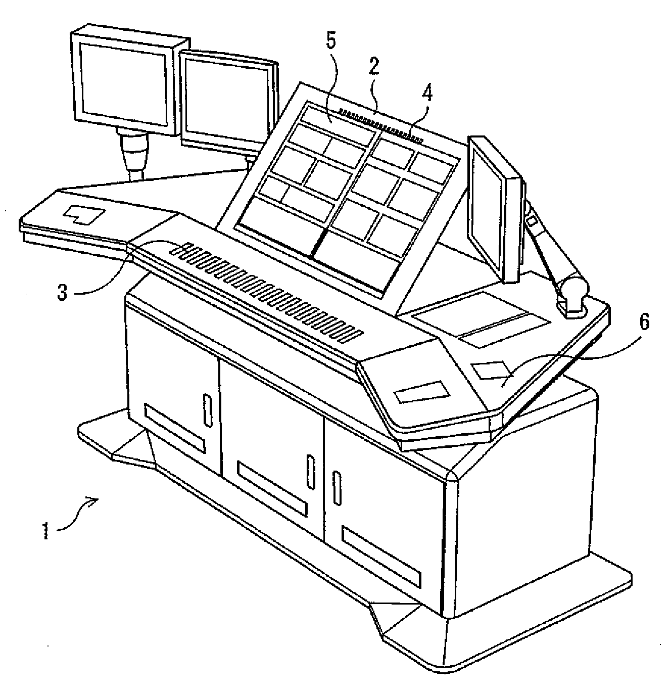
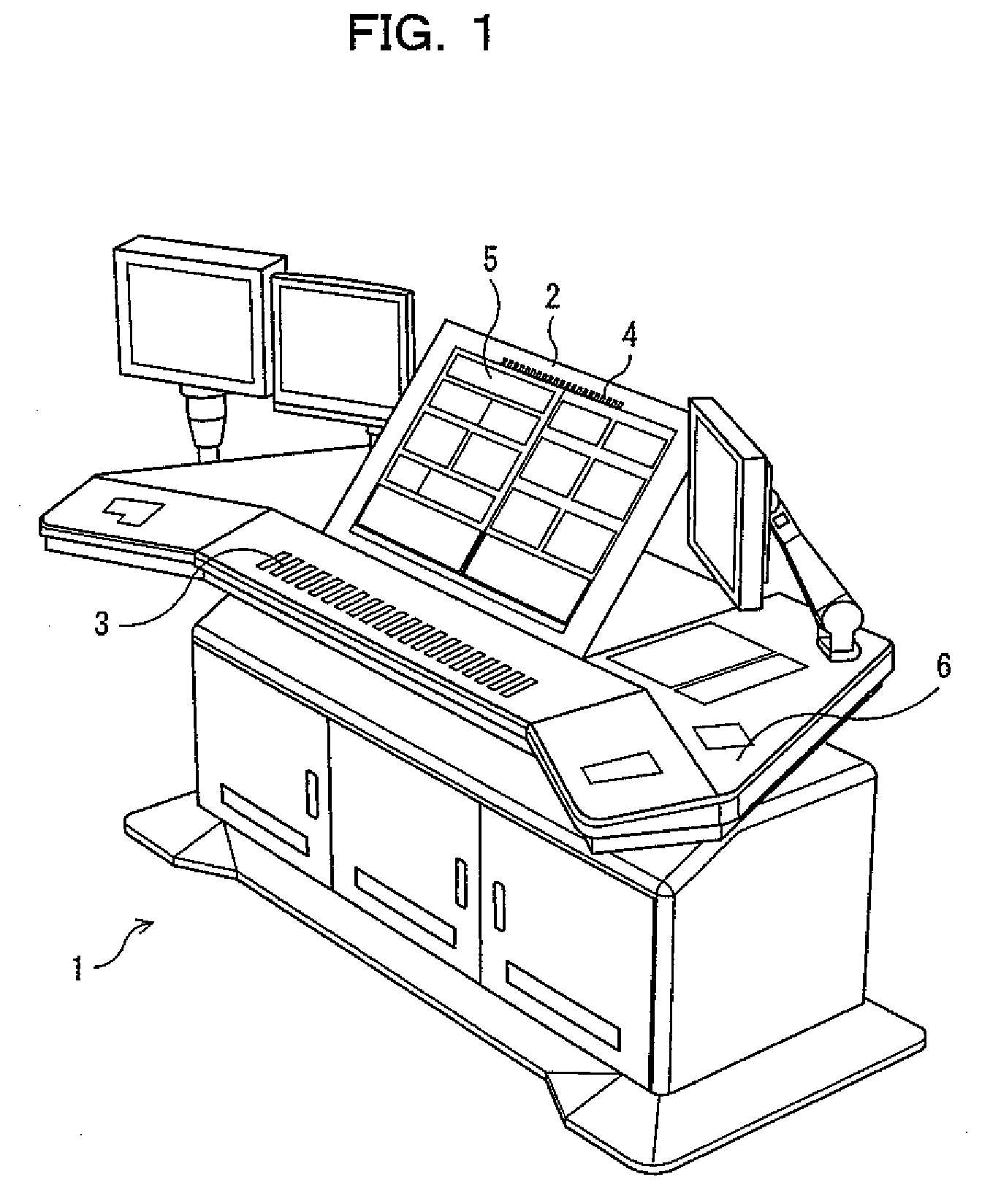
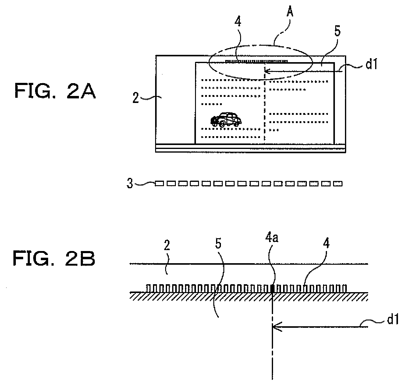
[0044]FIGS. 1 to 8 show a printing machine manipulation desk and a printing machine according to a preferred embodiment of the present invention, and based on these figures, the preferred embodiment will be described.

[0045](Printing Machine)

[0046]Referring initially to FIGS. 5 to 8, there is shown a rotary web printing machine that is a printing machine according to the preferred embodiment of the present invention. FIGS. 5 to 7 show the rotary web printing machine described in the aforementioned Patent Document 1. FIG. 5 is a plan view showing one of the rotary web printing machines arranged transversely, FIG. 6 is a front view of the rotary web printing machine shown in FIG. 5, and FIG. 7 is a plan view showing the relationship between a printing plate, a slitter, a turn bar, a paper press roller, and a triangular plate in the case of printing a web width (non-standard...


PUM


Abstract

A manipulation desk for controlling a supply of ink for each of a plurality of ink supply zones split in a width direction of printing paper in a printing machine. The manipulation desk includes a paper table for placing a sample printed paper thereon; a plurality of ink adjustment switches disposed so as to correspond to the ink supply zones along the width direction of the sample printed paper in front of a paper table; a plurality of indicators arranged on the paper table along the width direction of the sample printed paper; and a controller for selecting and lighting an indicator of the plurality of indicators that is used to position a specific position of the sample printed paper.

Description

BACKGROUND OF THE INVENTION[0001]1) Field of the Invention[0002]The present invention relates to a manipulation desk for controlling a supply of ink for each of a plurality of ink supply zones split in the width direction of printing paper in a printing machine, and more particularly to a manipulation desk for printing machines that can keep up with width changes of printing paper.[0003]2) Description of the Related Art[0004]In offset rotary web printing machines, the operator adjusts a supply of ink by hand to adjust the density and tone of images and characters that are printed. Such an ink supply adjustment is performed for each of the ink supply widths split in the axial direction of the printing cylinders (the plate cylinder and blanket cylinder), that is, in the printing width direction. The operator manipulates the ink supply adjustment switches provided so as to correspond to the ink supply widths, thereby adjusting a supply of ink.[0005]Particularly, in rotary presses for n...

Claims


Application Information

Patent Timeline
IPC IPC(8): B41J29/38
CPCB41F33/0009B41F33/00
Inventor KISHIGI, NOBUYUKIIKEDA, KAZUNORITOSHITO, TAKAHIDE
Owner MITSUBISHI HEAVY IND PRINTING & PACKAGING MACHINERY
Learn More