
Method for spatial color calibration using hybrid sensing systems

a color calibration and hybrid sensing technology, applied in the field of spatial color calibration using hybrid sensing systems, can solve the problems of macro uniformity defects, streaks, banding, etc., and achieve the effect of minimizing spatial uniformity errors and calibrating device color output spatially

Inactive Publication Date: 2008-02-14
XEROX CORP
View PDF3 Cites 98 Cited by
  • Summary
  • Abstract
  • Description
  • Claims
  • Application Information

AI Technical Summary

Benefits of technology

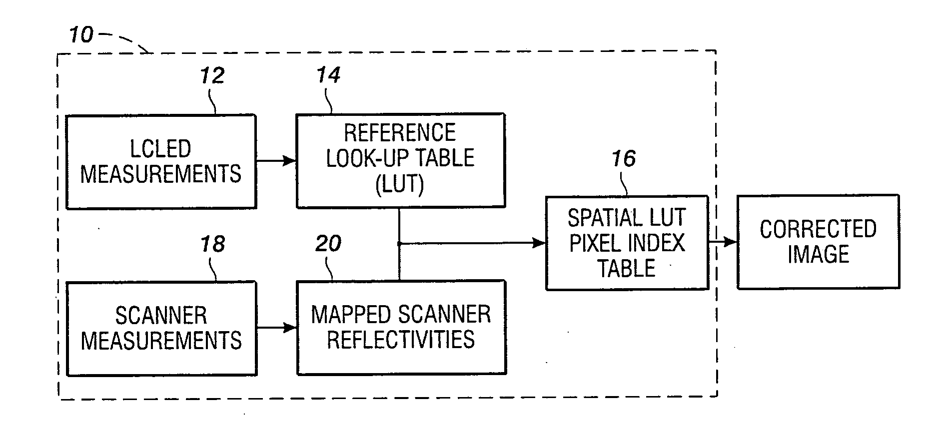
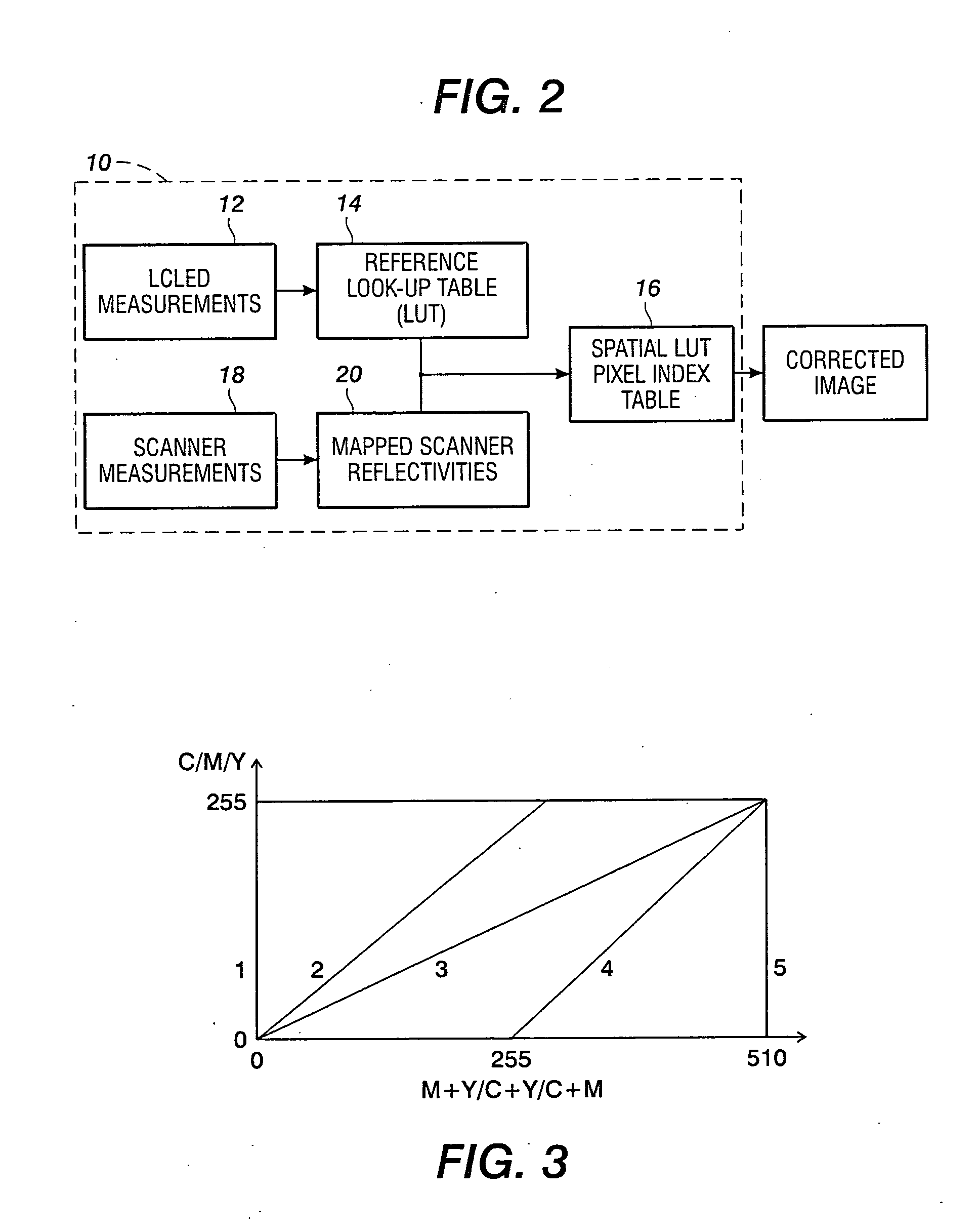
[0006]A second output image is produced with the device which includes the at least one preselected color at a plurality of spatial locations. A second sensor measures the image at the plurality of spatial locations corresponding to the preselected color to produce second output indicating reflectance information at the plurality of spatial locations. Errors are determined between the measured color of the one preselected color at the preselected location and the reflectance information at the other pixel locations. A multi-dimensional LUT is adjusted to minimize the spatial uniformity errors at the other pixel locations, thus calibrating device color output spatially whereby the device produces a more uniform color over a calibrated output image.
[0008]In another disclosed embodiment, a xerographic color output device comprises a controller for determining an error between the one preselected color and the measured color at another spatial location for adjusting the LUT of the device to minimize spatial uniformity errors, thereby calibrating the device color output spatially.

Problems solved by technology

Color rendering devices (e.g., a printer, copier, or other image output device) often have problems with macro uniformity defects, like streaks, banding, “smile / frown” defects, etc.
However, there is no suggestion in the application of extending such a spatial gray balanced calibration to a system of spatial color control methodology.

Method used


Image

  • Method for spatial color calibration using hybrid sensing systems
  • Method for spatial color calibration using hybrid sensing systems
  • Method for spatial color calibration using hybrid sensing systems

Examples


Embodiment Construction

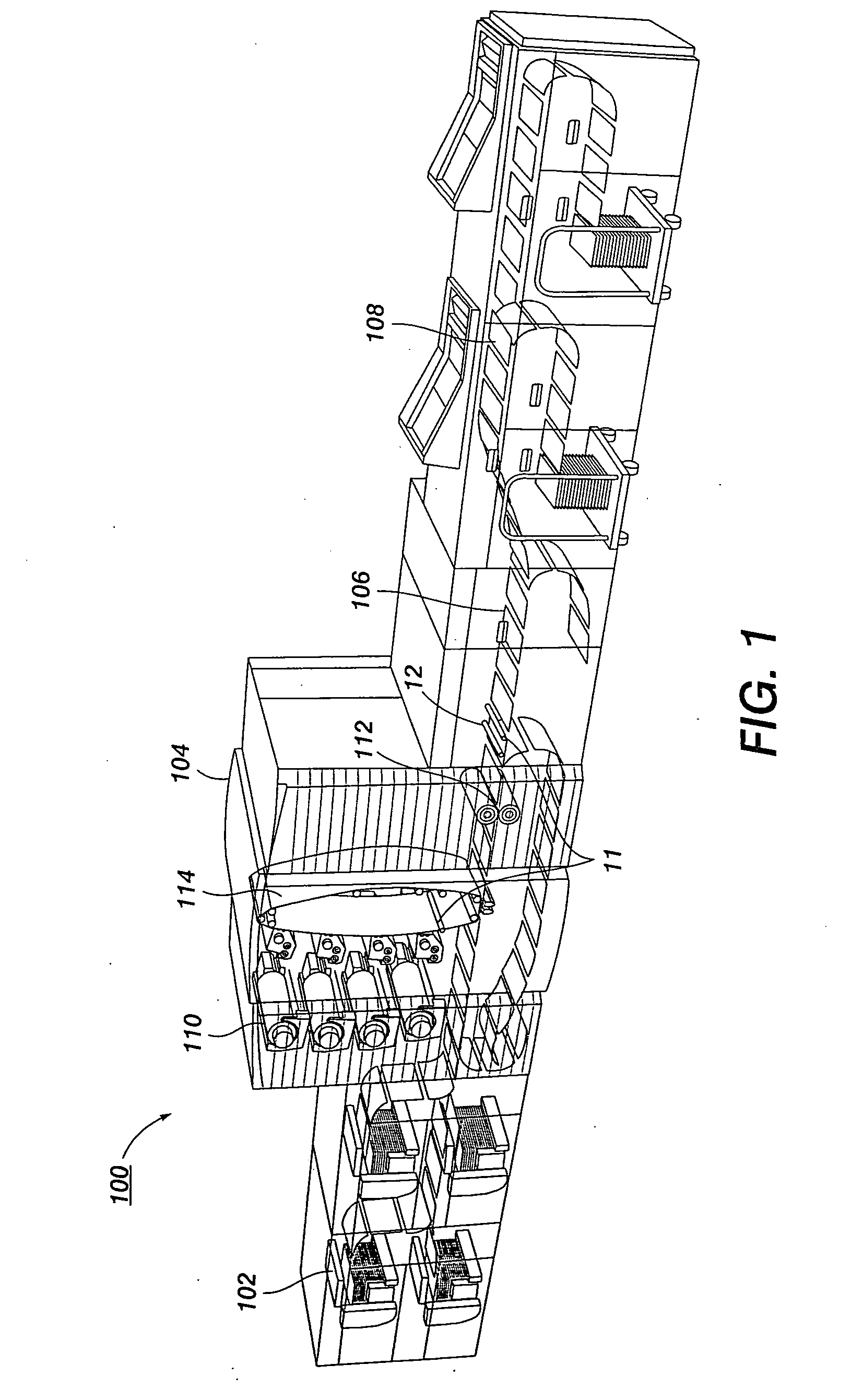
[0014]The system and method will be described in connection with preferred embodiments, however, it will be understood that there is no intent to limit the scope to the embodiments described. On the contrary, the intent is to cover all alternatives, modifications, and equivalents as may be included within the spirit and scope of the appended claims. Referring now to the drawings, the Figures show a method and apparatus for automatically calibrating a printing or similar output device.

[0015]The method and system use a combination of a full-width array (FWA) or similar page-scanning mechanism in conjunction with an on-line spectrophotometer color measurement system in the output path of a color printer for measuring colors (e.g., on printed test sheets, banner / separation pages, etc.) without requiring any manual operations or operator involvement The automatic color balance control system produces multi-dimensional LUT (Look-Up Table) values for the CMY primary colors by printing patc...


PUM


Abstract

A method and system for color calibration or color output device spectrophotoically measures at test target including a preselected test color value. A multi-dimensional LUT of the device is generated representative of the color information including the at least one preselected color. Producing a second image width device including the at least one preselected color located at a plurality of spatial locations in the second image. A second sensor measures the second image and a plurality of spatial locations having the preselected color for generating reflectance information for the preselected color at the plurality of spatial locations. An error is determined between the measured color of the one preselected color and the reflectance information at the other pixel locations. A multi-dimensional LUT is adjusted to minimize spatial uniformity errors at the other pixel locations, thus calibrating device color output spatially.

Description

BACKGROUND[0001]A method and system for printer color calibration are disclosed, and more particularly, a combination of a full-width array (FWA) or similar page-scanning mechanism in conjunction with an spectrophotometer color measurement system in the output path of a color printing system for measuring colors wherein spatial color maps are used to adjust multi-dimensional color look-up tables to obtain good color correction of macro uniformity defects.[0002]In many business applications, color documents have become essential as a component of communication. Color facilitates the sharing of knowledge and ideas. Companies involved in the development of color output devices continue to look for ways to improve the total image quality of such devices. One of the elements that affects the perception of image quality is an ability to consistently produce the same quality image output on a printer from one day to another, from one week to the next, month after month. Users are accustome...

Claims


Application Information

Patent Timeline
IPC IPC(8): G06K15/00
CPCH04N1/00045H04N1/00015H04N1/00002H04N1/00087H04N1/00068H04N1/6033H04N1/00058H04N1/00031H04N1/6041G06F15/00
Inventor MESTHA, LALIT KESHAVVITURRO, R. ENRIQUE
Owner XEROX CORP
Learn More