
Operation Device

a technology of operation device and illumination window, which is applied in the direction of instruments, lighting and heating apparatus, optical elements, etc., can solve the problems of difficult illumination of the plurality of illumination windows, and achieve the effect of high design freedom and compact and simple operation

Inactive Publication Date: 2008-02-14
KK TOKAI RIKA DENKI SEISAKUSHO
View PDF9 Cites 17 Cited by
  • Summary
  • Abstract
  • Description
  • Claims
  • Application Information

AI Technical Summary

Benefits of technology

[0010]The present invention provides a compact and simple operation device that illuminates a plurality of illumination windows and has a high level of design freedom.

Problems solved by technology

As a result, it becomes difficult to illuminate the plurality of illumination windows 57 with light having the same brightness.

Method used


Image

  • Operation Device
  • Operation Device
  • Operation Device

Examples


Embodiment Construction

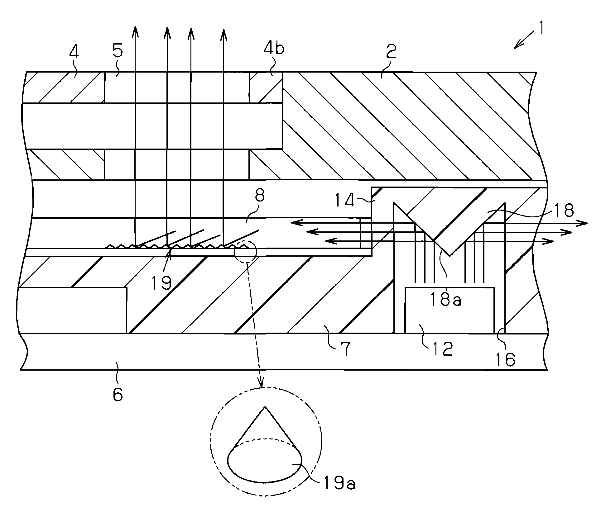
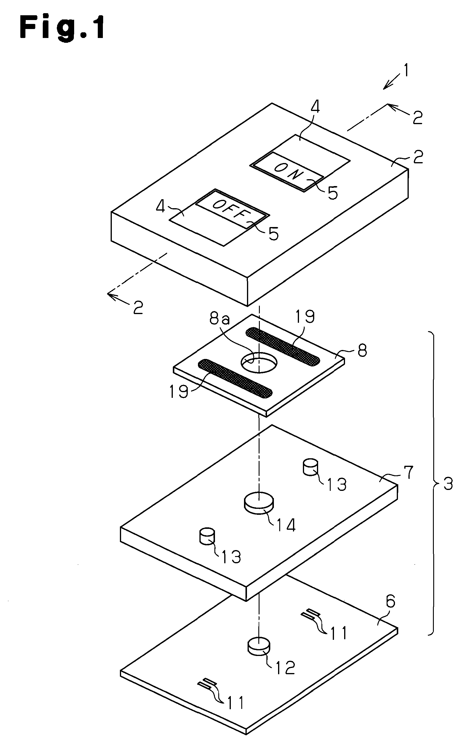
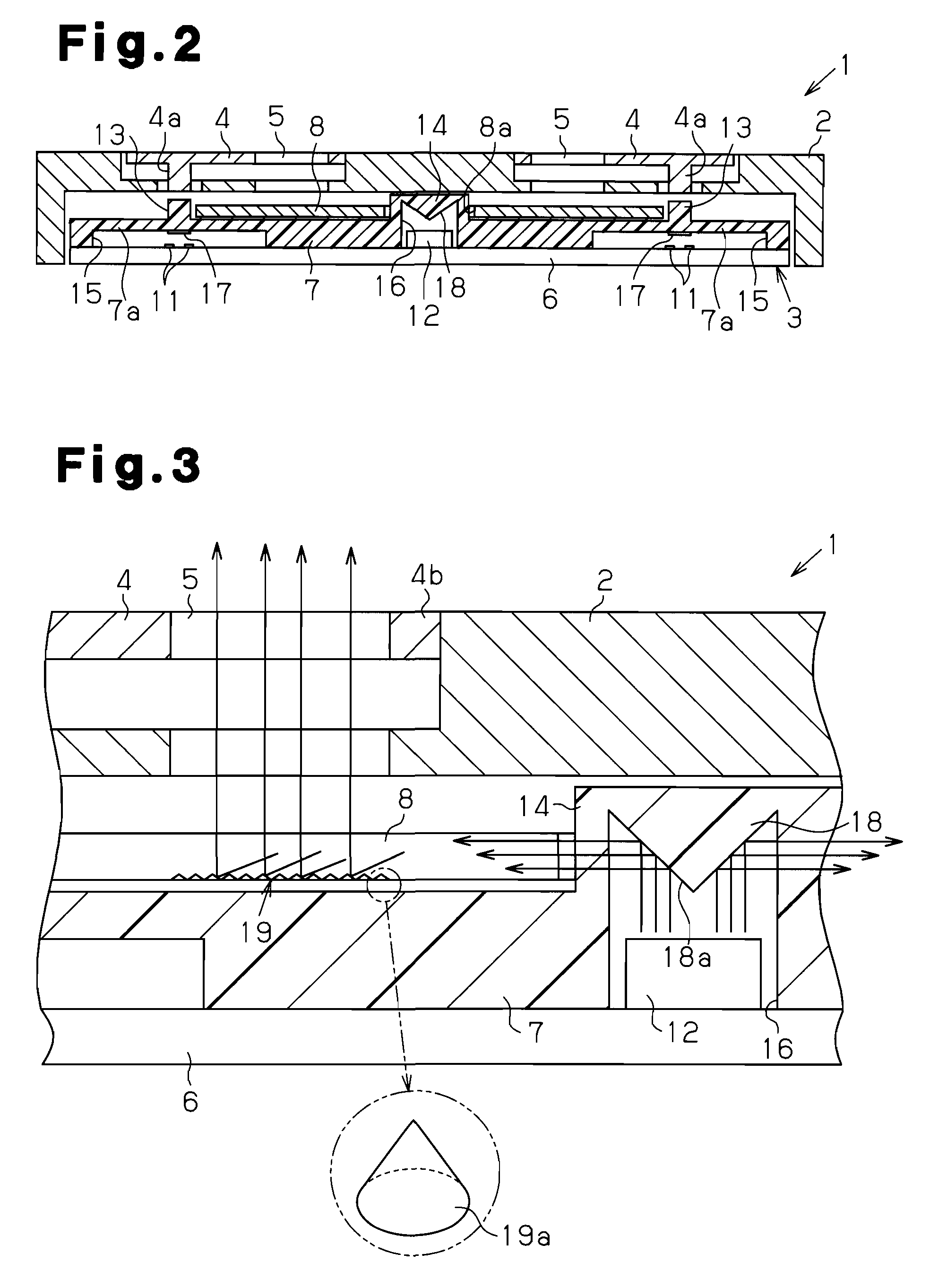
[0022]An operation device 1 according to a preferred embodiment of the present invention will now be discussed with reference to FIGS. 1 to 3.

[0023]Referring to FIG. 1, the operation device 1 includes a cover panel 2 and a switch assembly 3, which is arranged at the rear side (lower side as viewed in FIG. 1) of the cover panel 2. The operation device 1 is arranged, for example, near the driver's seat in a vehicle on a steering wheel or a dashboard.

[0024]As shown in FIG. 2, a plurality of (for example, two) operation portions 4 are exposed from the outer surface of the cover panel 2. Each operation portion 4 is supported by a hinge 4b (FIG. 3) in a manner tiltable relative to the cover panel 2. The operation portion 4 may be formed integrally with the cover panel 2.

[0025]An activation projection 4a extends downward from each operation portion 4. Each operation portion 4 includes a transparent or semi-transparent illumination window 5. The illumination window 5 may be a member that is...


PUM


Abstract

A single light source arranged in the central portion of an operation device illuminates operation portions and illumination windows of the operation device. The light emitted from the light source is reflected by a reflection surface of an elastic sheet into an inner side surface of a light guide plate. The light guide plate includes a plurality of light redirection areas for redirecting the light toward the illumination windows.

Description

CROSS-REFERENCE TO RELATED APPLICATIONS[0001]This application is based upon and claims the benefit of priority from prior Japanese Patent Application No. 2006-216968, filed on Aug. 9, 2006, the entire contents of which are incorporated herein by reference.BACKGROUND OF THE INVENTION[0002]The present invention relates to an operation device having a function for illuminating an operation portion.[0003]A typical operation device arranged in, for example, a passenger compartment of a vehicle illuminates an operation portion during the nighttime. This enables the position of the operation portion to be identified.[0004]Referring to FIG. 5, an operation device 51 of the prior art includes a cover panel 53 and a switch assembly 54, which is arranged at the rear side of the cover panel 53. The cover panel 53 includes a plurality of operation portions 52. A plurality of illumination windows 57 are respectively arranged adjacent to the plurality of operation portions 52. The switch assembly ...

Claims


Application Information

Patent Timeline
Patent Type & Authority Applications(United States)
IPC IPC(8): F21V7/04
CPCG02B6/0036G02B6/0081H01H2219/062H01H2219/056H01H2219/06H01H13/83
Inventor YAMAGUCHI, TATSUYUKIMIYAGAWA, AKIHITOWAKABAYASHI, JYUNYA
Owner KK TOKAI RIKA DENKI SEISAKUSHO
Learn More