
Security window or door with burglar-retardant features

Inactive Publication Date: 2008-02-21
SALZER SICHERHEITSTECHN
View PDF9 Cites 4 Cited by
  • Summary
  • Abstract
  • Description
  • Claims
  • Application Information

AI Technical Summary

Benefits of technology

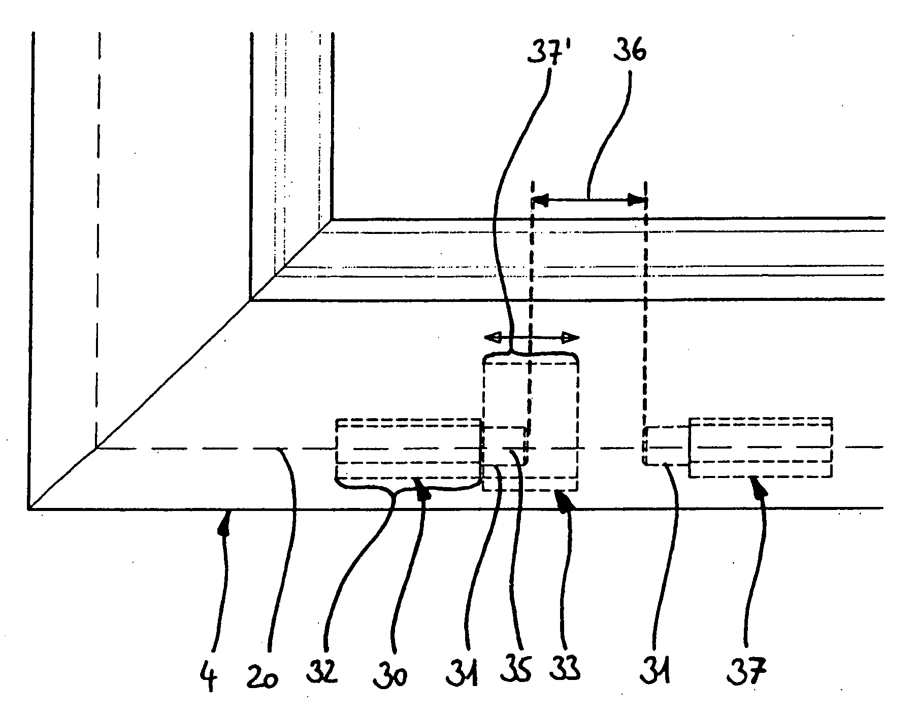
[0012] In a tilt-turn window, in the tilted position of the casement, a formfitting engagement between a locking element fixed on the frame and a locking element displaceable using the pushrod, which is a type of additional hinge and / or pivot joint, the rotational axis of this auxiliary joint being coincident with the tilt axis. The production of this additional form fit between casement and frame, which must be deactivated in the rotating position of the pushrod to allow the rotational movement of the casement, is performed very comfortably by actuating the pushrod, which is in turn typically actuated by a one-hand rotating handle. The user therefore does not notice the production of this additional form fit, but rather it occurs automatically upon the changeover between the rotating position and the tilted position. The advantage, in addition to the very high comfortability, is also that the production of this security-relevant additional form fit cannot be forgotten, which would affect the security properties very disadvantageously.
[0013] One advantage of the formfitting engagement according to the present invention in the form of an additional band and / or pivot joint is that it prevents a relative movement between casement and frame with very little play and / or almost without play in all directions perpendicular to the tilt axis. An auxiliary pivot joint of this type thus differs very advantageously from other locking elements engaging in one another in a formfitting way known from the prior art, for example, in the form of elements in the form of male and female molds or those having a groove-mushroom head engagement.
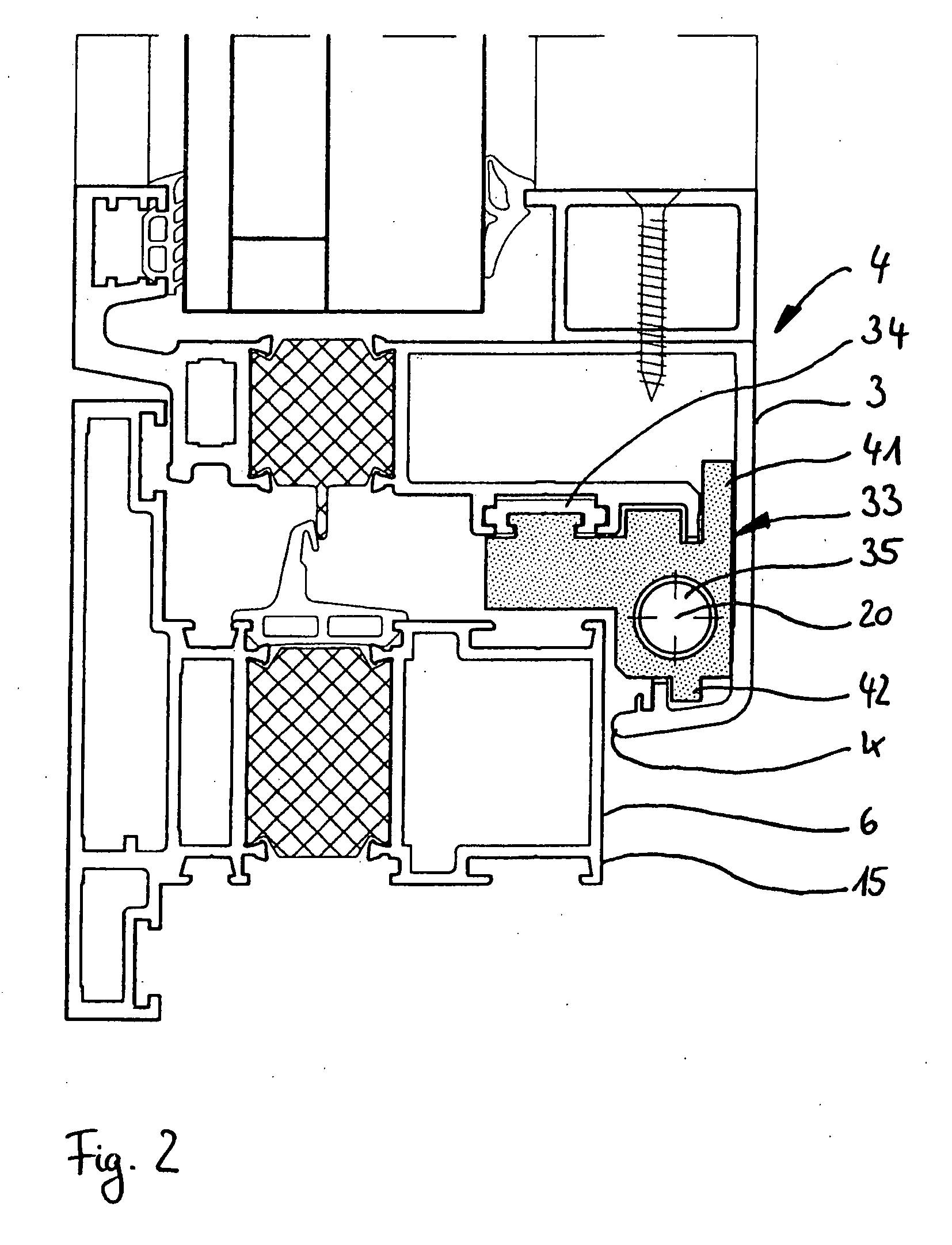
[0017] In this way, a very stable formfitting connection between the engagement area of the locking element and the coupling area thereof is provided. This is of special significance because the pushrod is typically only inadequately connected fixed to the bearing groove assigned thereto, so that even with a very loadable connection between the locking element and the pushrod, the latter could be torn out of the casement profile if the engagement area according to the present invention did not engage in a formfitting way in a chamber of the casement profile, so that in this case the strength of the walls of the casement profile is used.

Problems solved by technology

The advantage, in addition to the very high comfortability, is also that the production of this security-relevant additional form fit cannot be forgotten, which would affect the security properties very disadvantageously.

Method used


Image

  • Security window or door with burglar-retardant features
  • Security window or door with burglar-retardant features
  • Security window or door with burglar-retardant features

Examples


Embodiment Construction

[0027] Throughout all the Figures, same or corresponding elements are generally indicated by same reference numerals.

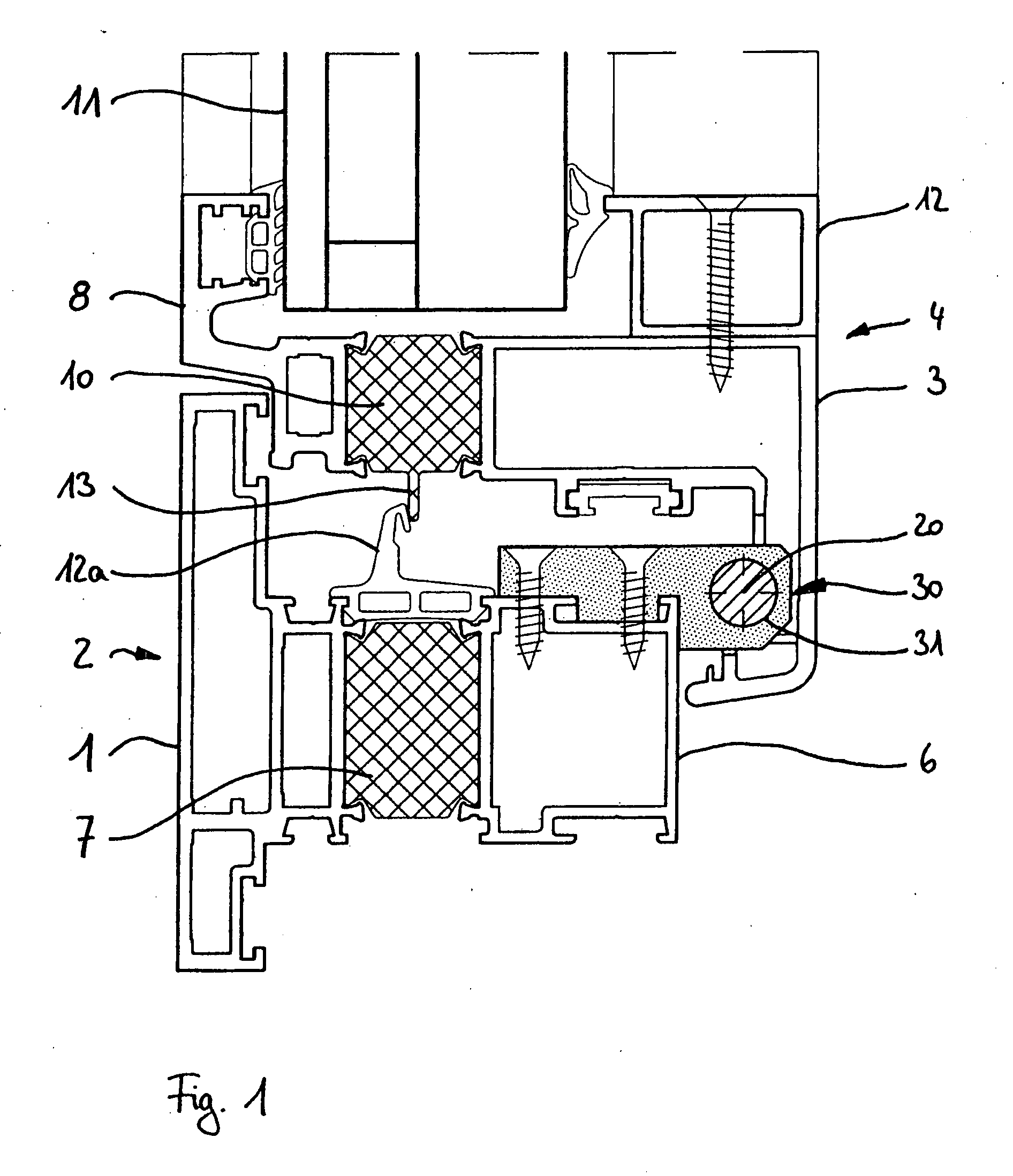
[0028] Turning now to the drawing, and in particular with reference to FIGS. 1 through 3, there is shown a security window which comprises a frame 2 anchored fixed in an opening of a building and a casement 4, provided with a filling 11 made of an insulating security glass, which is mounted in the frame 2 so it is tiltable around a horizontal tilt axis 20 and rotatable around a vertical rotational axis (not shown). On the side diametrically opposite the tilt axis, the casement 4 is connected using a security scissor hinge (not visible) to the frame 2, the security scissor hinge preventing further deflection in a tilt final position, in which the casement 4 is pivoted inward by a tilt angle of approximately 10° in relation to the frame 2, the security scissor hinge being under tension in this case.

[0029] The frame 2 comprises an external frame profile 1, which is cou...


PUM


Abstract

A security window or door has a first locking element fixedly coupled to a pushrod of a casement guided in a mortise area between the casement and a frame which is engaged in formfitting manner in a tilted position of the pushrod with a second locking element fixedly connected in the frame such that both locking elements are pivotable in relation to one another around a tilt axis and disengaged in a rotating position of the pushrod with the second element connected to the frame in fixed manner so that a rotational movement of the casement around the rotational axis is possible and wherein the first locking element is provided with either a pin engaged in a matching bearing hole of the second locking element or at least one bearing hole with which the pin of the second locking element may be engaged with a tilted or a closed position of the pushrod.

Description

CROSS-REFERENCES TO RELATED APPLICATIONS [0001] This application claims the priority of European Patent Application Serial No. 06 016 975, filed Aug. 15, 2006, pursuant to 35 U.S.C. 119(a)-(d), the subject matter of which is incorporated herein by reference. BACKGROUND OF THE INVENTION [0002] The present invention relates to a security window or a security door in a burglar-retardant embodiment, having a frame anchorable in an opening of a building and a casement provided with a filling and mounted in the frame so it is tiltable around a horizontal tilt axis and rotatable around a vertical rotational axis, whose tilt movement is delimited in a tilt final position by at least one security scissor hinge which connects the casement to the frame and is preferably attached on the side of the casement diametrically opposite the tilt axis, and having a first locking element coupled fixed to a pushrod of the casement guided concealed in a mortise area between the casement and the frame, whi...

Claims


Application Information

Patent Timeline
IPC IPC(8): E05B65/08
CPCE05C9/185E05Y2900/148E05D15/52
Inventor SALZER, HEINRICH
Owner SALZER SICHERHEITSTECHN
Learn More