Multi-scanner device having a detachable outlet tester

Active Publication Date: 2008-02-21
ECM IND LLC
View PDF10 Cites 19 Cited by
  • Summary
  • Abstract
  • Description
  • Claims
  • Application Information

AI Technical Summary

Benefits of technology

[0007]The present invention combines a detection unit and an outlet tester for convenient use and easy storage. The plug on the outlet teste

Problems solved by technology

However, the need for two separate tools creates a problem because the user needs to (1)

Method used


Image

  • Multi-scanner device having a detachable outlet tester
  • Multi-scanner device having a detachable outlet tester
  • Multi-scanner device having a detachable outlet tester

Examples


Example

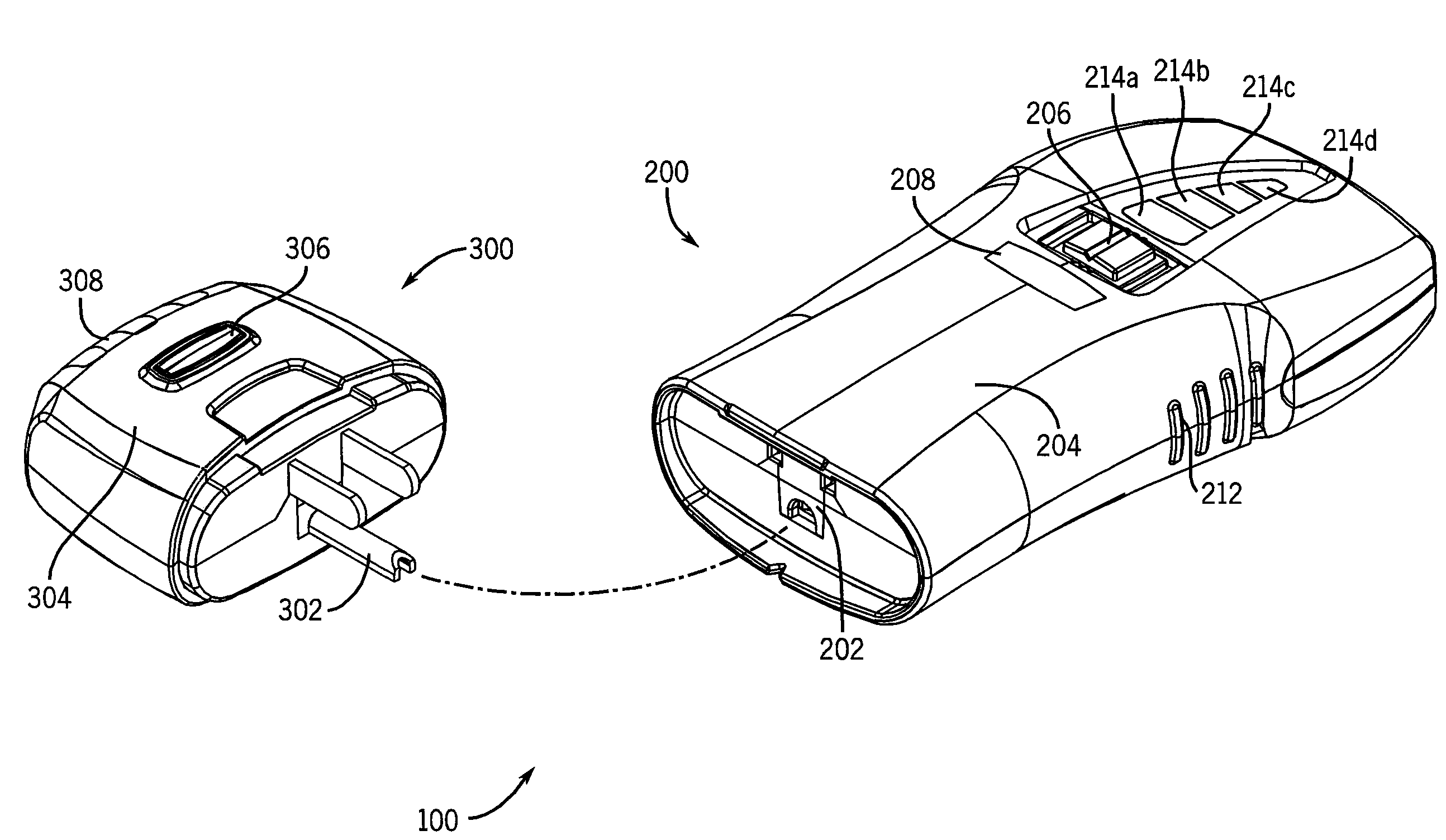
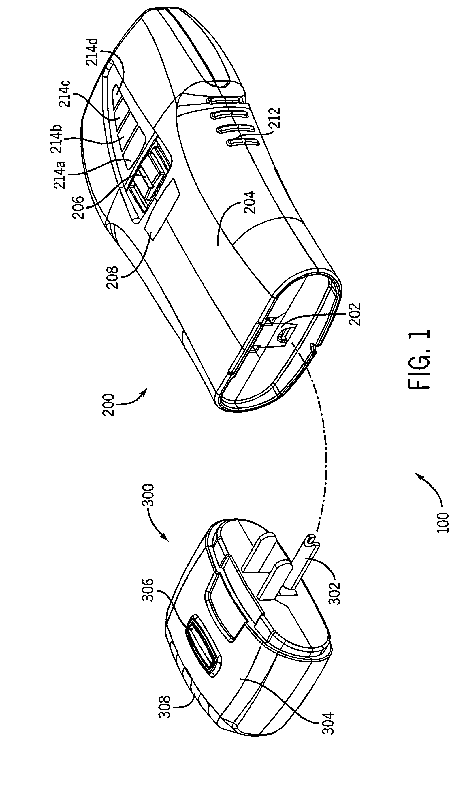
[0014]Referring now to FIG. 1, a multi-scanner device 100 includes a detection unit 200 and an outlet tester 300. The detection unit 200 includes circuitry for providing wood stud detection, metal detection, and a non-contact AC voltage detection as described below. The outlet tester 300 provides an outlet wiring test and a ground fault circuit interrupter test. The detection unit 200 has an interface that can be, as shown here, a socket 202, and the outlet tester 300 has a mating plug 302. When the outlet tester 300 is not in use, the plug 302 can be inserted in the socket 202 for easy storage of the outlet tester 300.

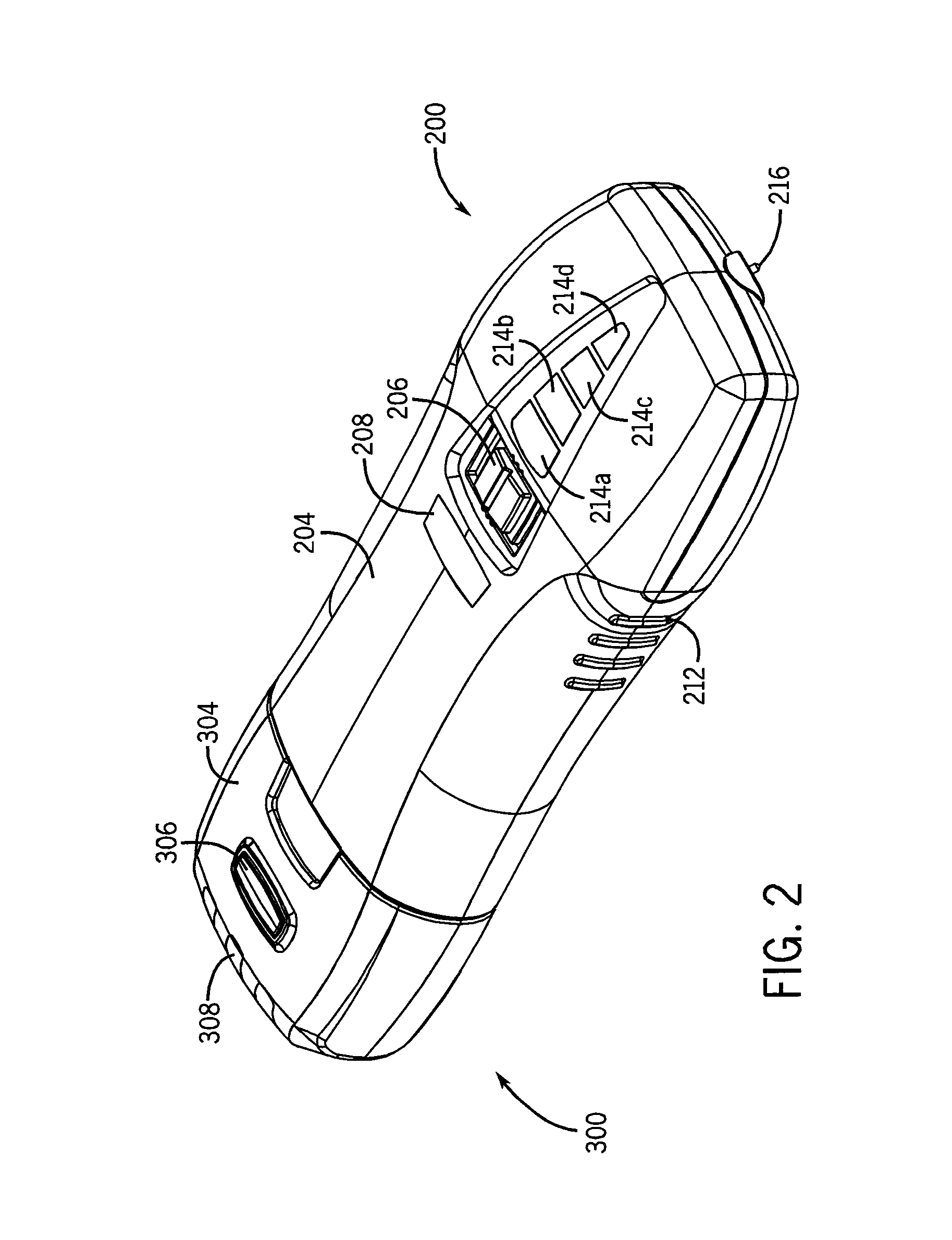
[0015]The detection unit 200 has a housing 204 in which the circuitry for performing the available scanning modes is encased. A scan mode switch 206 is located on the front face of the detection unit 200. The scan mode switch 206 permits the user of the detection unit 200 to toggle among the available scanning modes. In FIG. 1 the scan mode switch 206 is a three-way s...


PUM


Abstract

A multi-scanner device having a detection unit and an outlet tester that can be selectively connected together for convenient use and easy storage. Preferably, a plug on the outlet tester is inserted into a non-functional socket located on the detection unit to form a multi-scanner device with a detachable outlet tester.

Description

CROSS-REFERENCE TO RELATED APPLICATIONS[0001]This application claims the benefit of U.S. Provisional Patent Application No. 60 / 822,701 filed Aug. 17, 2006.STATEMENT REGARDING FEDERALLY SPONSORED RESEARCH OR DEVELOPMENT[0002]Not ApplicableBACKGROUND OF THE INVENTION[0003]Wall sensors and scanners, such as stud finders, are well-known and commonly used by tradesmen and do-it-yourselfers in construction projects to locate objects located below the surface of a wall. One type of stud finder is a single mode electronic stud finder, which typically includes a capacitor for detecting changes in the capacitance as the stud finder moves across the surface of the wall. A change in capacitance indicates that the dielectric constant of the surface has changed due to the presence of an object behind the surface of the wall.[0004]In addition to single mode wall scanners, multifunction detection units have been developed which can be toggled between various modes of detection. For example, in addi...

Claims


Application Information

Patent Timeline
IPC IPC(8): G01R31/04
CPCG01R31/045G01R31/69
Inventor RADLE, PATRICK J.BROCKMAN, DARYL C.WIESEMANN, DAVID L.
Owner ECM IND LLC
Why Eureka
Try Eureka