
Image forming apparatus

a technology of forming apparatus and forming plate, which is applied in the direction of electrographic process apparatus, thin material processing, instruments, etc., can solve the problems of inability to hold a predetermined amount of sheets, inability to completely increase the thickness of sheets, and high cost of correcting mechanism

Inactive Publication Date: 2008-02-21
KYOCERA DOCUMENT SOLUTIONS INC
View PDF5 Cites 21 Cited by
  • Summary
  • Abstract
  • Description
  • Claims
  • Application Information

AI Technical Summary

Benefits of technology

[0011]In view of the above problems residing in the prior art, it is an object of the invention to provide an image forming apparatus that enables to prevent a sheet stacking capacity of a discharge tray from lowering resulting from a curl of a sheet discharged on the discharge tray.

Problems solved by technology

When the curl is formed on the sheet, the entire thickness of the sheet may be unduly increased, with the result that the discharge tray may be incapable of holding a predetermined amount of sheets.
Secondly, the curl correcting mechanism may be costly, which may resultantly increase the production cost of the image forming apparatus.
As result, the sheet processing performance of the image forming apparatus may be degraded.

Method used


Image

  • Image forming apparatus
  • Image forming apparatus
  • Image forming apparatus

Examples


Embodiment Construction

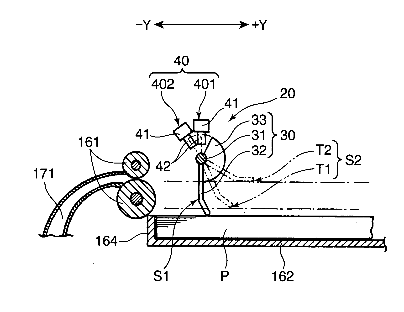
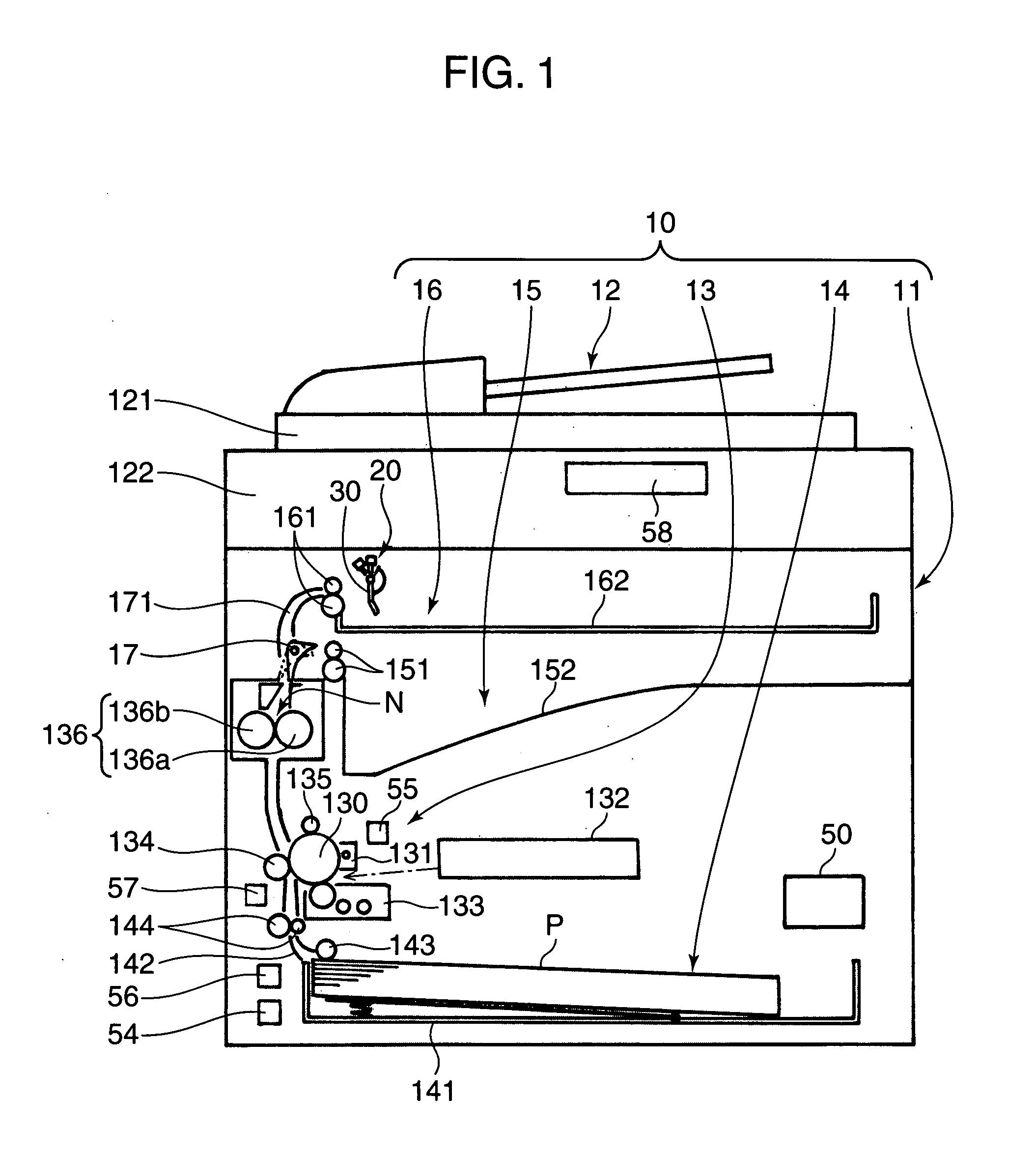
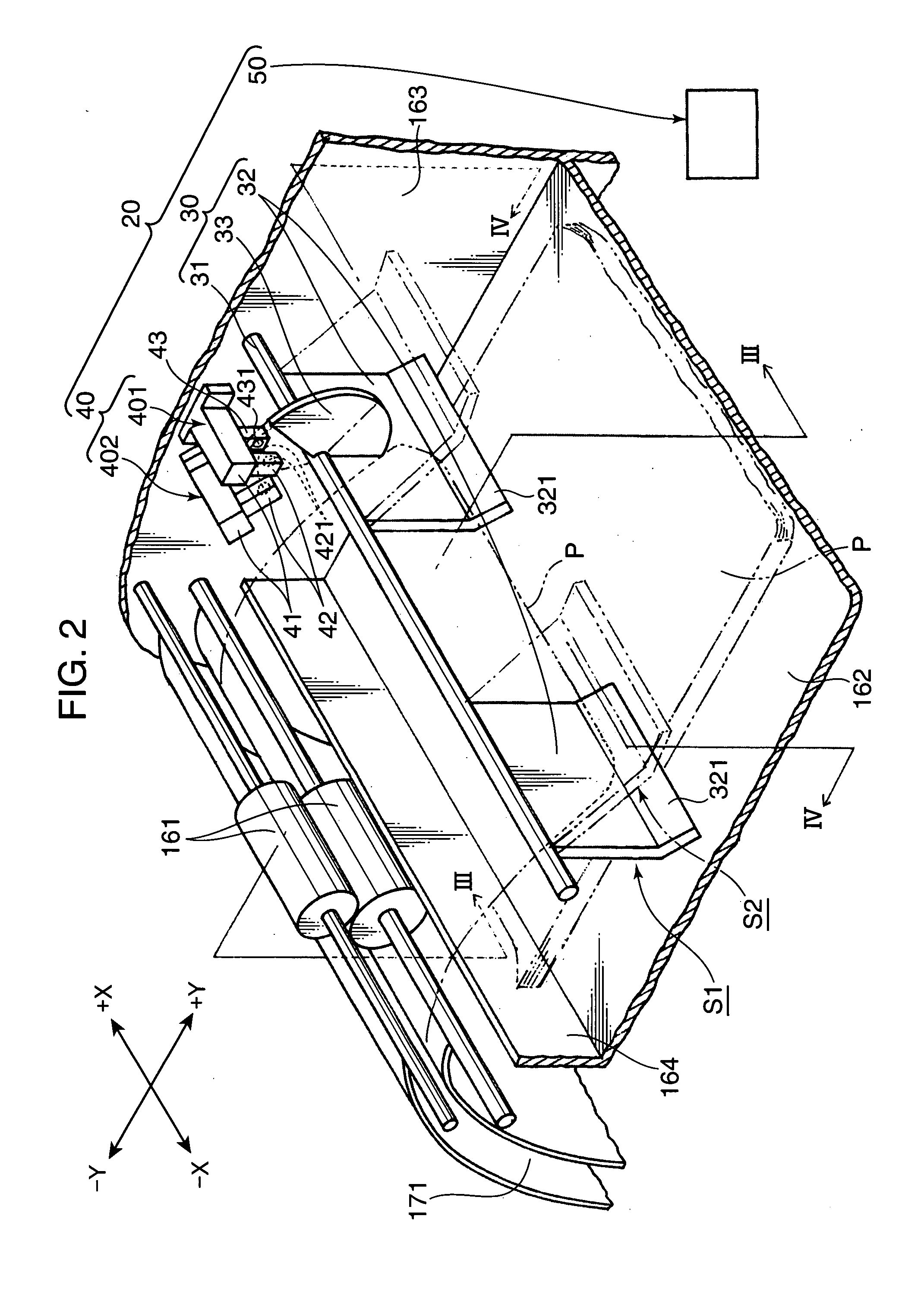
[0020]FIG. 1 is a cross-sectional view schematically showing an internal structure of a copier 10, as an example of an image forming apparatus embodying the invention. In this embodiment, the copier 10 is a complex machine provided with various functions such as a facsimile function in addition to a copying function.

[0021]As shown in FIG. 1, the copier 10 i.e. the image forming apparatus 10 has a box-shaped main body 11, in which a document reader 12, an image former 13, a sheet feeder 14, a primary discharging portion 15, and a job separator discharging portion 16 or a secondary discharging portion 16 are provided. The document reader 12 is provided on a top part of the copier main body 11. The image former 13 is provided substantially in the middle of the copier main body 11. The sheet feeder 14 is provided at a position below the image former 13 in the copier main body 11. The primary discharging portion 15 is formed immediately above the image former 13, and is integrally formed...


PUM


Abstract

An image forming apparatus includes: an image former for performing an image formation by transferring a toner image onto a sheet; a fixing unit for performing a fixing operation with respect to the sheet having the transferred toner image by heating; a discharge tray for successively stacking the sheet to be discharged after the fixing operation; and a curl correcting mechanism for correcting a curl of the sheet to be discharged onto the discharge tray after the fixing operation.

Description

BACKGROUND OF THE INVENTION[0001]1. Field of the Invention[0002]The present invention relates to an image forming apparatus provided with a sheet curl correcting mechanism.[0003]2. Description of the Related Art[0004]An electrophotographic image forming apparatus is constructed in such a manner that: an electrostatic latent image is formed on the surface of a photosensitive drum by light irradiation from an exposure device based on predetermined image information; a toner image is formed on the surface of the photosensitive drum by supplying toner particles onto the electrostatic latent image by a developing device; and the toner image is transferred onto a sheet. Then, the toner image transferred to the sheet is fixed by a fixing device, followed by discharge of the sheet carrying the fixed toner image.[0005]The fixing device includes a fixing roller internally provided with a heater for heating the fixing roller, and a pressure roller disposed as opposed to the fixing roller, with...

Claims


Application Information

Patent Timeline
IPC IPC(8): G03G15/00
CPCG03G15/6576B65H31/26
Inventor NAKAJIMA, EIJI
Owner KYOCERA DOCUMENT SOLUTIONS INC
Learn More