Thermal management device

Active Publication Date: 2017-12-07
DENSO CORP
View PDF1 Cites 14 Cited by
  • Summary
  • Abstract
  • Description
  • Claims
  • Application Information

AI Technical Summary

Benefits of technology

[0009]Thus, if the amount of heat dissipation into the heat medium at one heat dissipation device can be estimated to increase, the flow rate of the heat medium flowing through the heat dissipation device is increased. Thus, w

Problems solved by technology

According to studies by the inventors of the present disclosure, in the related art, heat dissipation into the coolant is carried out in each of the intercooler and condenser, and thereby if the amount of heat dissipation in the intercooler is large, the coolant cooling capacity of the radiator tends to become insufficien

Method used


Image

  • Thermal management device
  • Thermal management device
  • Thermal management device

Examples


first embodiment

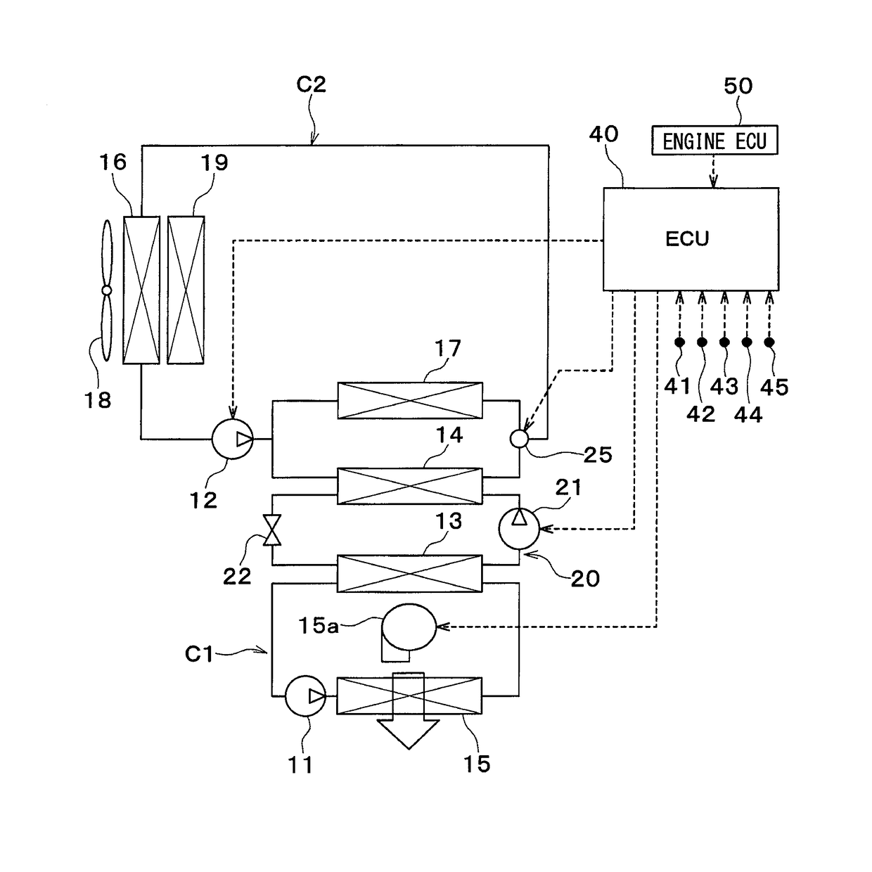
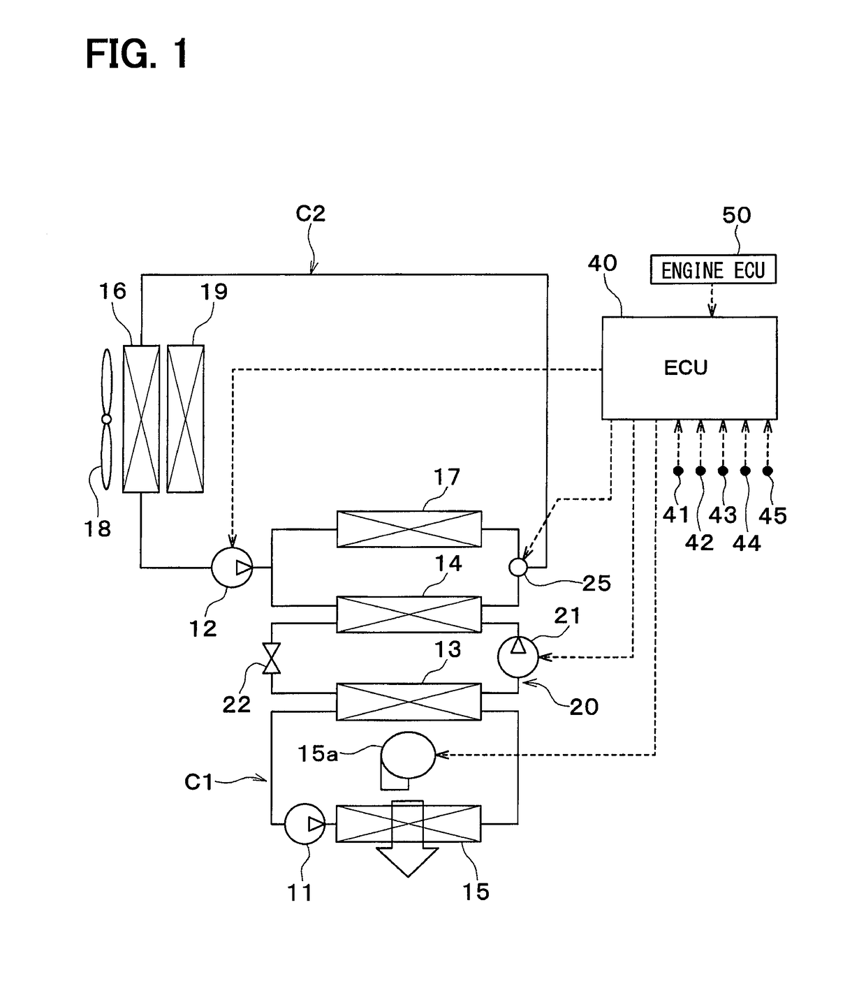
[0024]A first embodiment will be described below based on FIGS. 1 to 3. A vehicle thermal management device shown in FIG. 1 is used to adjust various devices mounted on a vehicle or an interior of the vehicle to an appropriate temperature.

[0025]The vehicle thermal management device includes a first pump 11, a second pump 12, a chiller 13, a condenser 14, a cooler core 15, a radiator 16, and an intercooler 17.

[0026]Each of the first pump 11 and the second pump 12 is an electric pump that draws and discharges a coolant (heat medium). The coolant is a fluid as the heat medium. In the embodiment, the coolant suitable for use includes a liquid containing at least ethylene glycol, dimethylpolysiloxane, or a nanofluid, or an antifreezing solution.

[0027]The chiller 13, the condenser 14, the cooler core 15, the radiator 16, and the intercooler 17 are coolant circulation devices (heat-medium circulation devices) through which the coolant circulates.

[0028]The chiller 13 is a low-pressure side ...

second embodiment

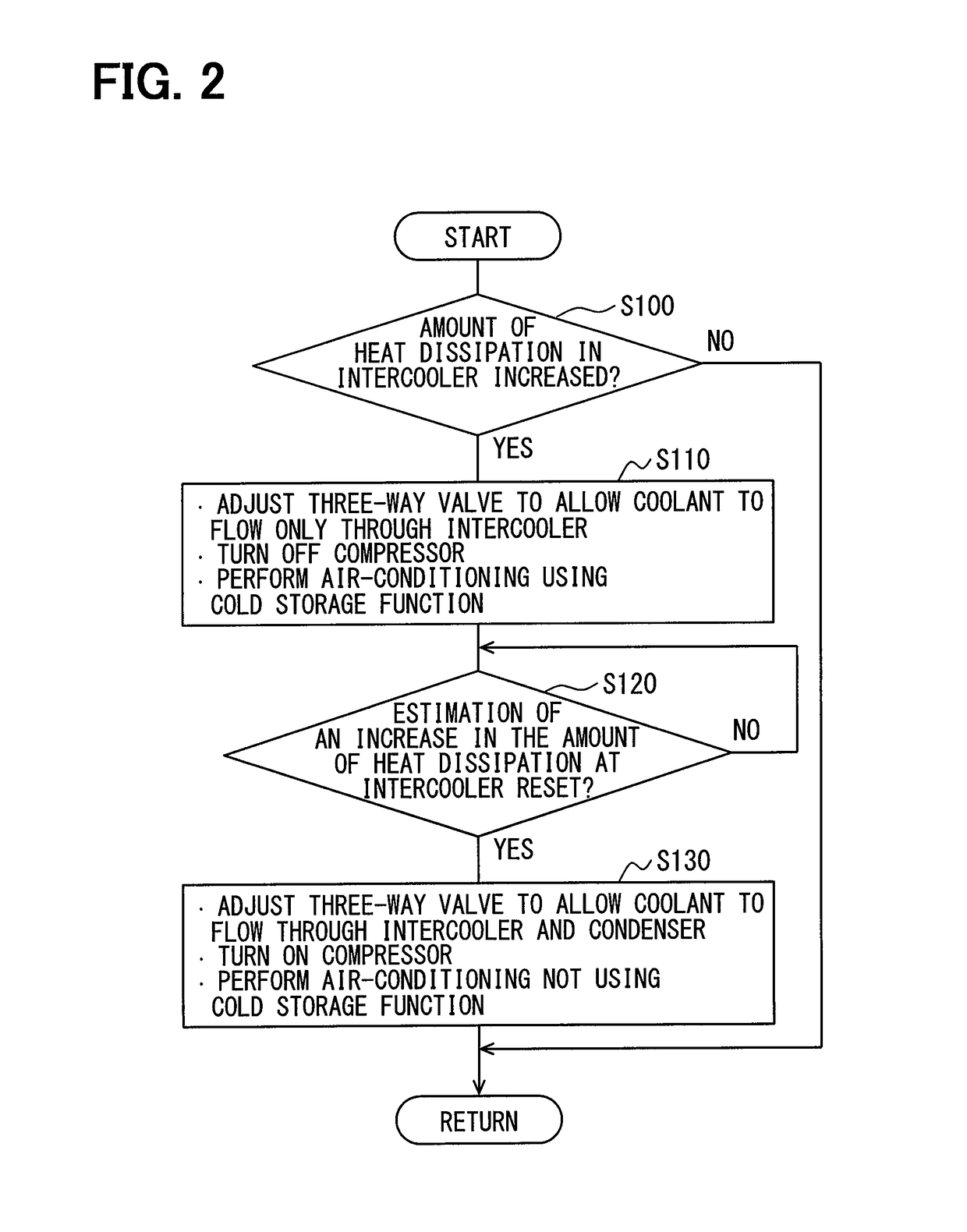
[0096]In the embodiment, as shown in FIG. 4, the intake-air cooling priority control in step S111 is carried out as follows. (1) The operation of the three-way valve 25 is controlled to allow the coolant to flow through the intercooler 17 but not through the condenser 14. (2) The compressor 21 is stopped. (3) The cooler core 15 cools the air by using a cold storage function of the first coolant circuit C1. (4) The volume of air blown by the interior blower 15a is reduced.

[0097]Thus, the volume of air flowing through the cooler core 15 is reduced, thereby decreasing the temperature of the air cooled by the cooler core 15. Therefore, the cooling comfort in the vehicle interior can be further maintained.

[0098]In step S130, to reset the intake-air cooling priority control, the following control is carried out. (1) The operation of the three-way valve 25 is controlled to allow the coolant to flow through both the intercooler 17 and the condenser 14. (2) The compressor 21 is operated. (3)...

third embodiment

[0103]Although in the first embodiment, the three-way valve 25 adjusts the flow rate of the coolant flowing through the intercooler 17, in the embodiment, as shown in FIG. 5, a two-way valve 26 adjusts the flow rate of the coolant flowing through the intercooler 17.

[0104]The two-way valve 26 is disposed in a coolant flow path on the condenser 14 side, selected from the coolant flow paths (i.e., two coolant flow paths arranged in parallel) on the condenser 14 side and the intercooler 17 side. Thus, the two-way valve 26 adjusts the opening of the coolant flow path on the condenser 14 side. The two-way valve 26 is capable of opening and closing the coolant flow path on the condenser 14 side.

[0105]That is, the two-way valve 26 is a flow-rate ratio adjustment device that adjusts the ratio of the flow rate of the coolant flowing through the condenser 14 to that through the intercooler 17. In other words, the two-way valve 26 is a flow-rate adjustment device that adjusts the flow rate of t...


PUM


Abstract

A thermal management device includes two or more heat dissipation devices that dissipate heat into a heat medium, a heat medium-air heat exchanger that exchanges heat between air and the heat medium having its heat dissipated in the two or more heat dissipation devices, a flow-rate adjustment device that adjusts a flow rate of the heat medium flowing through the heat dissipation device, and a control unit. The control unit controls an operation of the flow-rate adjustment device to increase the flow rate of the heat medium flowing through the one heat dissipation device, if the control unit estimates an increase in the amount of heat dissipation into the heat medium at the one heat dissipation device of the two or more heat dissipation devices.

Description

CROSS REFERENCE TO RELATED APPLICATION[0001]This application is based on Japanese Patent Application No. 2014-234800 filed on Nov. 19, 2014, the contents of which are incorporated herein by reference in its entirety.FIELD OF THE INVENTION[0002]The present disclosure relates to a thermal management device through which a heat medium circulates.BACKGROUND ART[0003]Conventionally, for example, non-patent document 1 describes a thermal management device in which an intercooler, a condenser, and a radiator are disposed in the same coolant circuit.[0004]The intercooler is a heat exchanger that cools the intake air to the engine by dissipating heat from the intake air into a coolant. The condenser is a heat exchanger that cools a refrigerant by dissipating heat from the refrigerant into a coolant in a refrigeration cycle. The radiator is a heat exchanger that cools the coolant by exchanging heat between the outside air and the coolant having the heat exchanged in both the intercooler and c...

Claims


Application Information

Patent Timeline
IPC IPC(8): B60H1/32B60K11/04B60H1/00F25B1/10
CPCB60H1/323B60K11/04B60H1/00764F25B2600/0251F25B1/10F25B2339/047F25B2500/26B60H1/3213B60K11/02F25B1/00B60H1/32284
Inventor MIURA, KOJIKATOH, YOSHIKISUGIMURA, KENGOKAKEHASHI, NOBUHARU
Owner DENSO CORP
Why Eureka
Try Eureka