
Ship steering device

A technology of steering gear and rudder shaft, applied in the field of steering gear, can solve the problems of increased power consumption and heat generation, and achieve the effect of suppressing the generation of power consumption and heat generation

Active Publication Date: 2011-05-25
MITSUBISHI HEAVY IND LTD
View PDF8 Cites 15 Cited by
  • Summary
  • Abstract
  • Description
  • Claims
  • Application Information

AI Technical Summary

Problems solved by technology

However, if the capacity of the booster pump 26 is increased, there is a problem that the power consumption and the calorific value accompanying the operation of the pump will also increase, so it is not preferable.

Method used


Image

  • Ship steering device
  • Ship steering device
  • Ship steering device

Examples


Embodiment Construction

[0054] One embodiment of the steering gear of the present invention will be described with reference to the drawings.

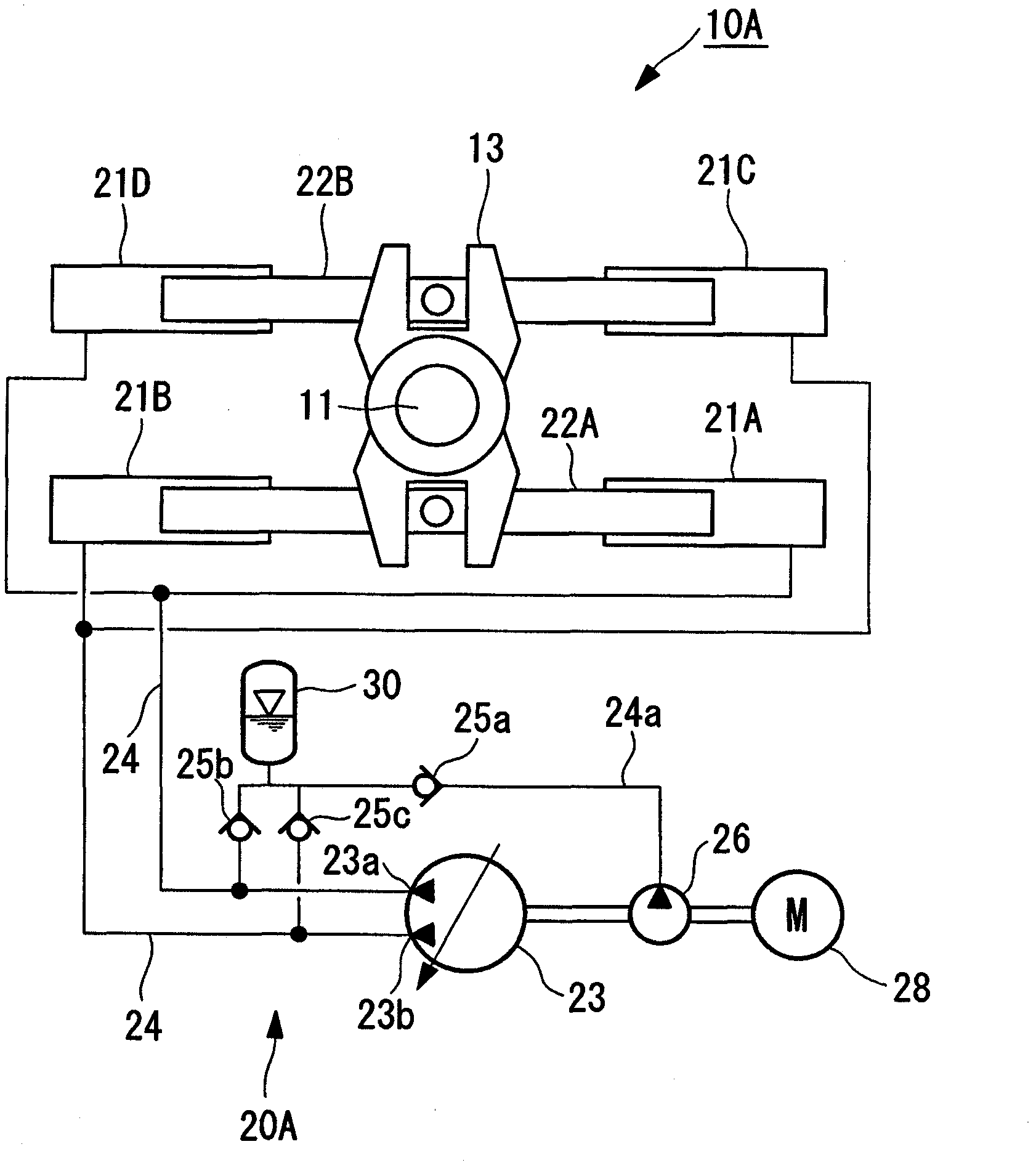
[0055] Such as figure 1 The illustrated electrohydraulic steering gear 10A drives a rudder shaft 11 rotatably supported on the navigating body and a rudder plate 12 ( refer to Figure 4 ) for the steering gear used. This steering gear 10A is equipped with four hydraulic cylinders 21 (21A, 21B, 21C, and 21D when it needs to be distinguished) connected to the hydraulic system 20A as actuators that serve as drive mechanisms for turning the rudder shaft 11, as actuators. It is not limited to a hydraulic cylinder, and may be a rotary vane or the like.

[0056] In addition, reference numeral 13 in the figure is a rudder stock which rotates the rudder shaft 11 in conjunction with the hydraulic cylinder 21 .

[0057] The hydraulic system 20A described above includes: a main hydraulic pump 23 capable of changing the suction / discharge direction and discharge flow r...


PUM


Abstract

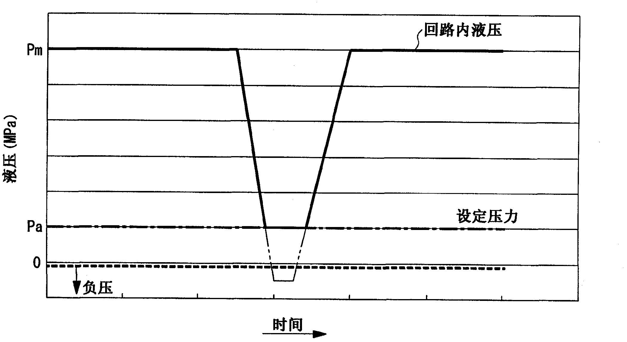
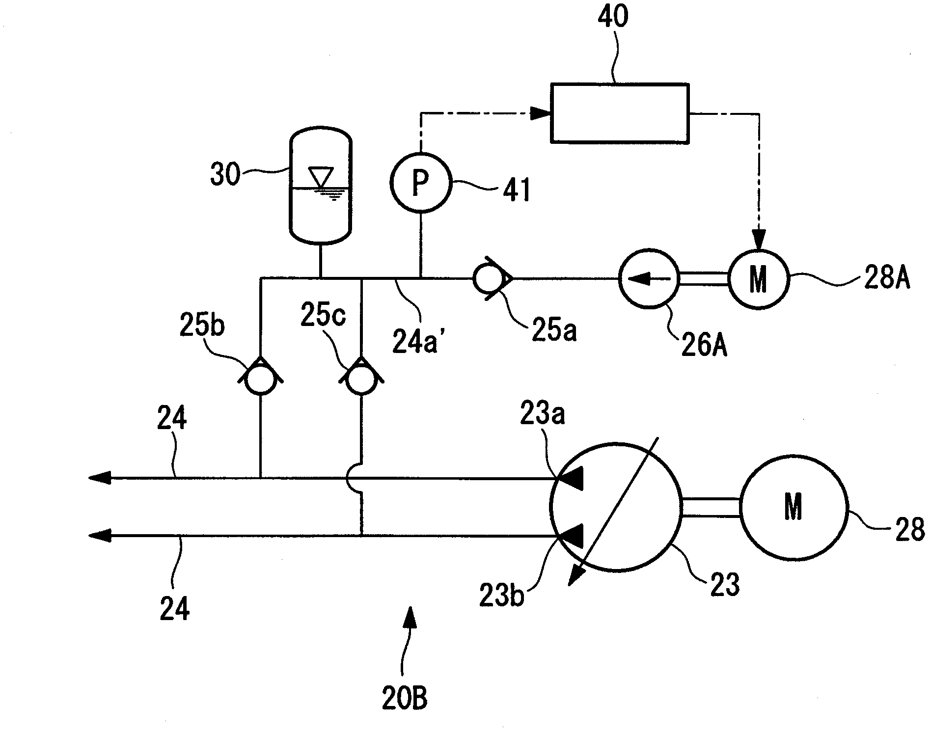
The invention provides a ship steering device in which cavitation in a main hydraulic pump due to a negative pressure region in a hydraulic circuit is prevented to avoid generation of noise caused by the cavitation. The ship steering device (10A) causes a rudder shaft (11) and a rudder plate to pivot. The rudder shaft (11) is pivotably supported by the ship, and the rudder plate is fixed to the rudder shaft (11) and pivots together with the rudder shaft (11). A drive mechanism for causing the rudder shaft (11) to pivot has hydraulic actuators (21A, 21B, 21C, 21D) connected to a hydraulic system (20A). The hydraulic system (20A) has the main hydraulic pump (23) in which the direction of suction and discharge of oil and the flow rate of oil discharged can be changed, a boost pump (26) for maintaining the pressure in the hydraulic system (20A) at a predetermined level, and an accumulator (30) as hydraulic pressure storage means for preventing cavitation in the main hydraulic pump (23) caused by formation of a negative pressure region in the hydraulic system (20A).

Description

technical field [0001] The present invention relates to a steering gear that is equipped on a navigation body such as a ship to steer the steering wheel. Background technique [0002] When a navigable body such as a ship changes its direction of travel, steering is performed to manipulate the direction (angle) of a rudder plate arranged at the rear of the bottom of the ship or the like. Among steering gears (steering devices) that perform such steering, there is an electrohydraulic system that includes a hydraulic system that generates hydraulic pressure using a hydraulic pump driven by an electric motor and controls the hydraulic pressure acting on a hydraulic cylinder to actuate a steering plate. [0003] Regarding the steering gear using the electrohydraulic method, Figure 4 and Figure 5 Indicates a conventional configuration example. [0004] For example Figure 4 As shown, the steering gear 10 is provided with the rudder shaft 11 which protrudes downward from the sh...

Claims


Application Information

Patent Timeline
Patent Type & Authority Applications(China)
IPC IPC(8): B63H25/30F04B23/02F04B49/00F15B11/02
CPCB63H25/30F15B2211/7128F15B2211/20576F15B2211/20546F15B2211/7107
Inventor 时津智史佐佐木数幸
Owner MITSUBISHI HEAVY IND LTD
Learn More