Tubular medical instrument

a medical instrument and tube technology, applied in the field of tube medical instruments, can solve the problems of increasing manufacturing costs and difficult handling during assembly, and achieve the effect of facilitating installation

Active Publication Date: 2008-02-21
KARL STORZ GMBH & CO KG
View PDF4 Cites 14 Cited by
  • Summary
  • Abstract
  • Description
  • Claims
  • Application Information

AI Technical Summary

Benefits of technology

[0014]Correctly seated insertion of the shaft end into the insertion bore-hole, in particular with respect to the alignment to the snap-on device, can be facilitated according to the invention in that at least one guide element is positioned in the handle, to serve to align the proximal end of the hollow shaft in the insertion bore-hole, so that the guide element preferably is configured as a rod or, for instance, as a headless screw that can be screwed into the handle.
[0015]According to a practical embodiment of the invention, on the proximal end of the hollow shaft at least one guide groove is configured for insertion of the guide element. Two guide grooves for inserting the guide el

Problems solved by technology

Snap-on connections in themselves, as a rule, involve a certain free play when they are not manufactured with ext

Method used


Image

  • Tubular medical instrument
  • Tubular medical instrument
  • Tubular medical instrument

Examples


Embodiment Construction

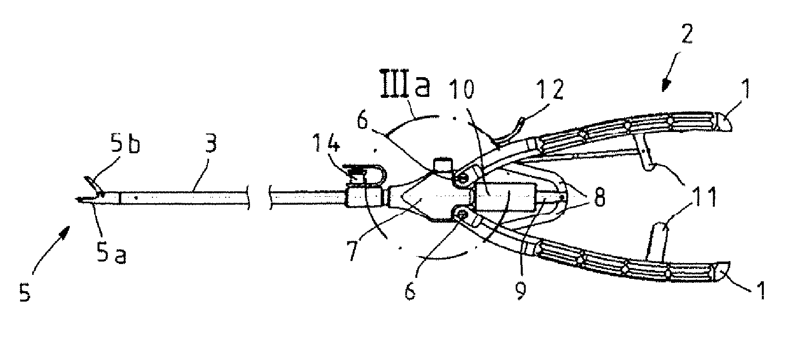
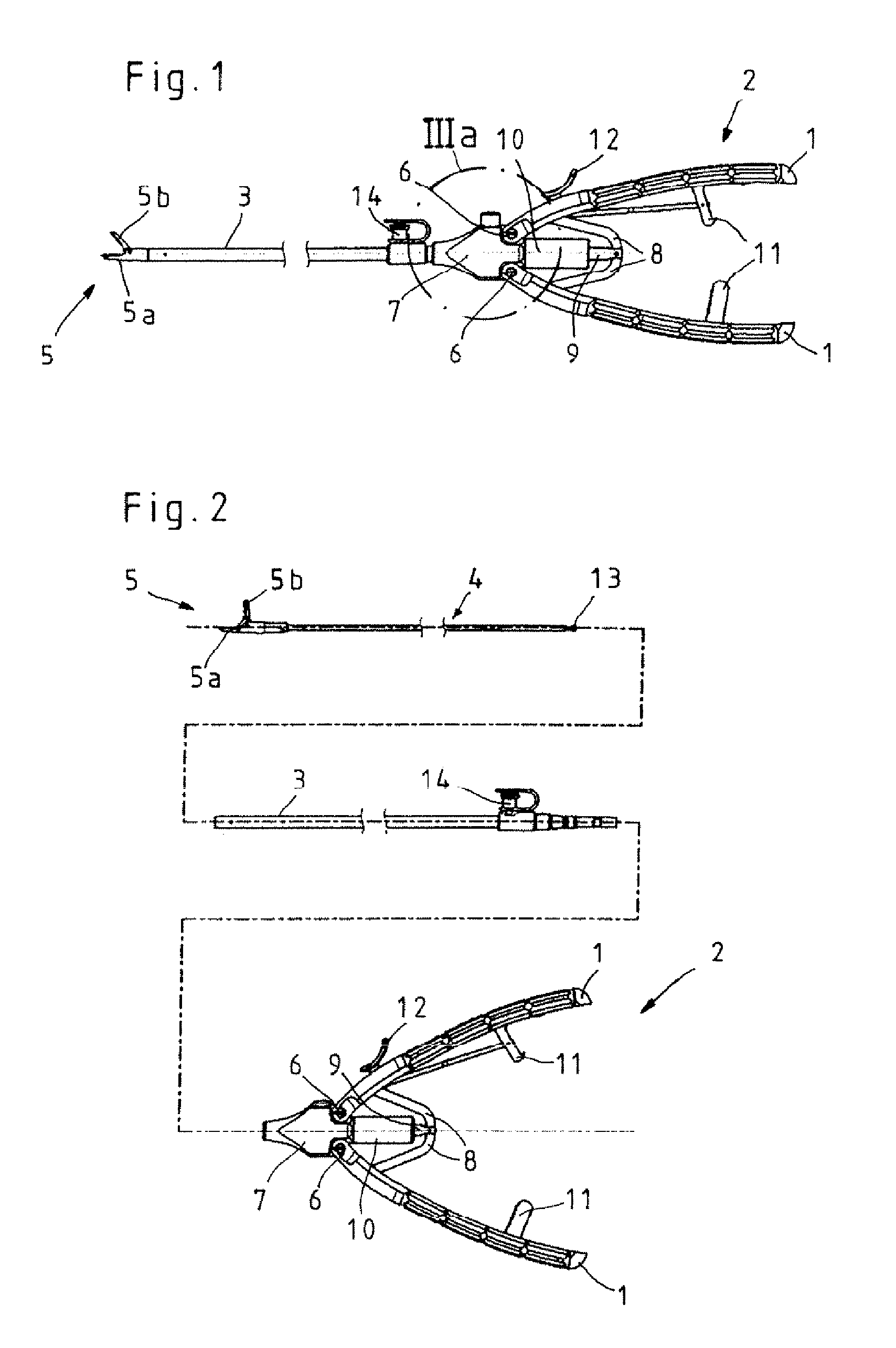
[0025]The tubular medical instrument shown in FIGS. 1 and 2, configured as a needle holder, consists essentially of a handle 2 equipped with two gripping members 1, a hollow shaft 3, and a push-pull rod 4 that can be inserted into the hollow shaft 3 and has on its distal end a tool 5 consisting of two jaw members 5a and 5b.

[0026]The tubular medical instrument shown in FIGS. 1 and 2 in the form of a needle holder consists essentially of a handle 2 equipped with two gripping members 1, a hollow shaft 3, and a push-pull rod 4 that can be inserted in the hollow shaft 3 and has on its distal end a tool 5 consisting of two jaw members 5a and 5b.

[0027]The three components handle 2, hollow shaft 3, and push-pull rod 4, which are particularly clearly depicted in FIG. 2, can be coupled with one another by coupling and snap-on mechanism in such a way that by actuation of the gripping members 1 of the handle 2 the jaw members 5a and 5b of the tool 5 can be moved between an open and a closed w...


PUM


Abstract

The invention relates to a tubular medical instrument having a hollow shaft, a handle equipped with at least two gripping members and positioned on the proximal end of the shaft, and at least one push-pull rod that is mounted in the hollow shaft and has a tool consisting of at least two jaw members. For opening and closing at least one jaw member of the tool, said push-pull rod can be coupled with at last one rotatable gripping member of the handle, and the hollow shaft and handle can be releasably connected to one another by means of a coupling mechanism. To create a coupling mechanism that is simple to operate, it is proposed with the invention that the coupling mechanism should be configured as a combined clamping and snap-on device.

Description

CROSS-REFERENCE TO RELATED APPLICATIONS[0001]The present application claims priority of German patent application No. 10 2006 038 517.9 filed on Aug. 17, 2006, the content of which is incorporated herein by reference.FIELD OF THE INVENTION[0002]The invention relates to a tubular medical instrument having a hollow shaft, a handle equipped with at least two gripping members and positioned on the proximal end of the shaft, and at least one push-pull rod that is mounted in the hollow shaft and has a tool consisting of at least two jaw members. For opening and closing at least one jaw member of the tool, said push-pull rod can be coupled with at last one rotatable gripping member of the handle, and the hollow shaft and handle can be releasably connected to one another by means of a coupling mechanism.BACKGROUND OF THE INVENTION[0003]Tubular medical instruments of this type are in use in endoscopic surgery, for instance in the configuration as needle holder. Because of more stringent hygi...

Claims


Application Information

Patent Timeline
IPC IPC(8): A61B17/28
CPCA61B17/00234A61B17/2909A61B2017/00477A61B2217/007A61B2017/292A61B2019/4868A61B2217/005A61B2017/2901A61B2090/0813
Inventor RENGER, UWEBLOCHER, MARTINBACHER, UWE
Owner KARL STORZ GMBH & CO KG
Why Eureka
Try Eureka