
One-Way Clutch with Dog-Clutch and Synchronizer

a one-way clutch and dog-clutch technology, applied in the field of vehicle transmission, can solve the problems of affecting the smoothness and efficiency of gear shifting, and/or imparting high impact loading

Inactive Publication Date: 2008-02-28
GM GLOBAL TECH OPERATIONS LLC
View PDF4 Cites 24 Cited by
  • Summary
  • Abstract
  • Description
  • Claims
  • Application Information

AI Technical Summary

Benefits of technology

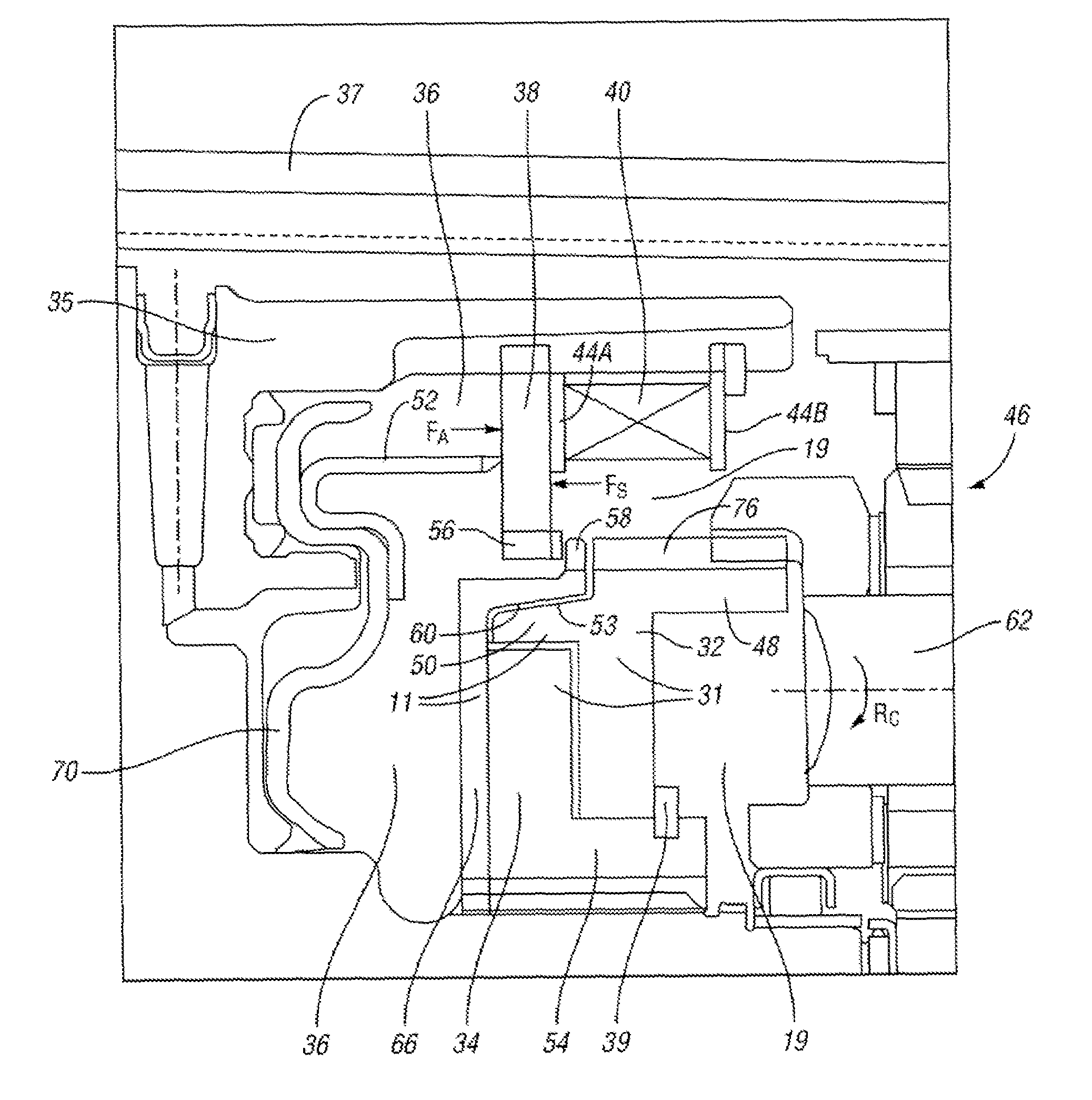
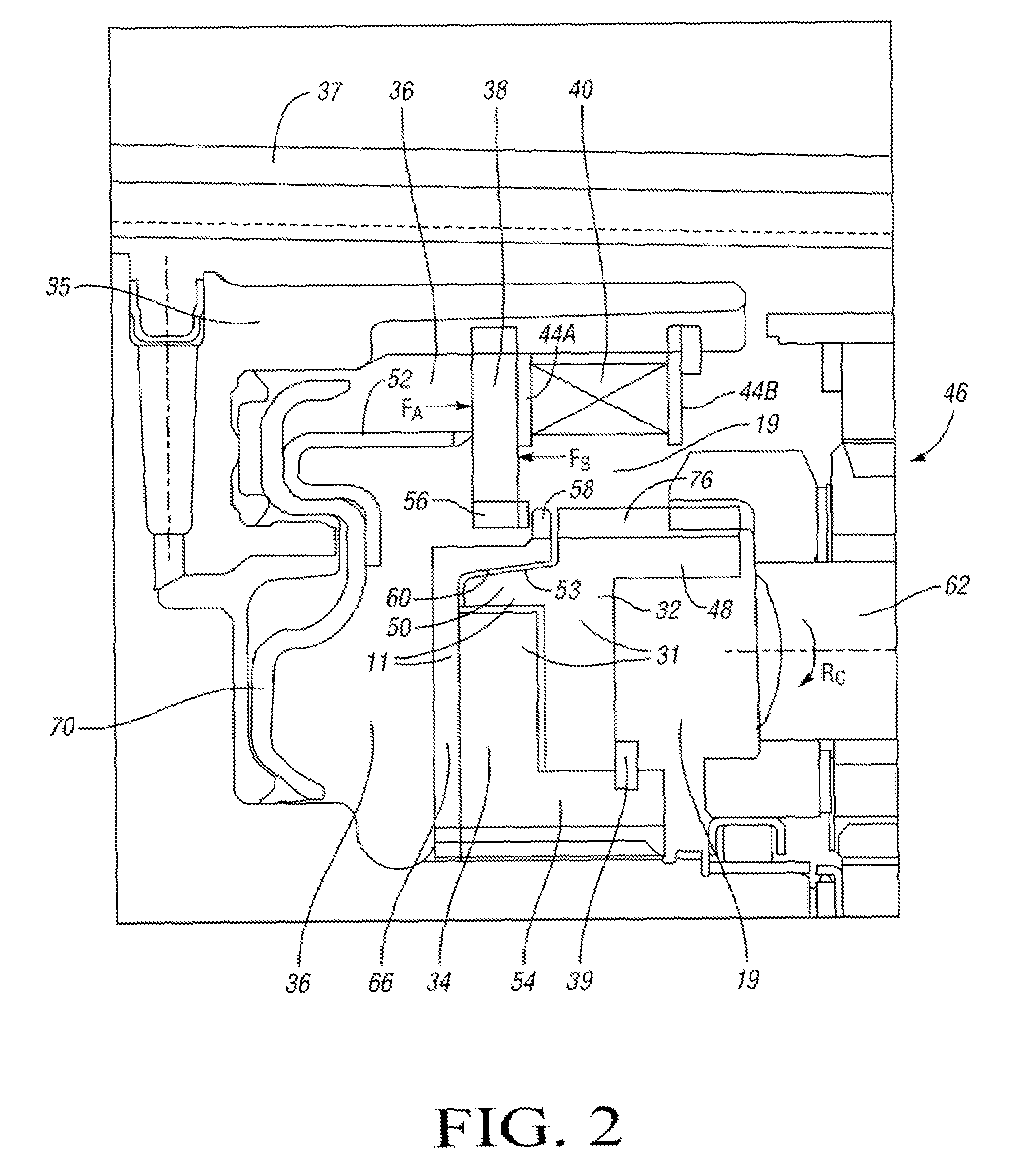
[0009]In another aspect of the invention, a vehicle is provided including an automatic transmission, a controller, and a controllable clutch assembly including a one-way clutch, a clutch-apply mechanism, a synchronizer clutch having a synchronizer plate and clutch synchronizer, and a dog clutch having a hub and an apply plate. The clutch-apply mechanism is configured to move the apply plate into engagement with the synchronizer plate in response to the controller, wherein the synchronizer plate is matable with the clutch synchronizer to thereby synchronize the rotational speeds of the one-way clutch and apply plate in order to optimize the gear shifting efficiency of the transmission.

Problems solved by technology

However, due to the inherent inability of a one-way clutch to hold torque in two rotational directions, a redundant clutch, commonly referred to as a “coast clutch”, may be employed in tandem with the one-way clutch specifically to hold or retain the torque in the opposite or reverse rotational direction, such as during vehicle coasting and under certain reverse rotational conditions.
However, selective clutching devices may not be optimal for synchronizing the disparate relative rotational speeds of the outer and inner clutch races, which if not optimally synchronized may adversely affect gear shifting smoothness and efficiency, and / or impart high impact loading.

Method used


Image

  • One-Way Clutch with Dog-Clutch and Synchronizer
  • One-Way Clutch with Dog-Clutch and Synchronizer
  • One-Way Clutch with Dog-Clutch and Synchronizer

Examples


Embodiment Construction

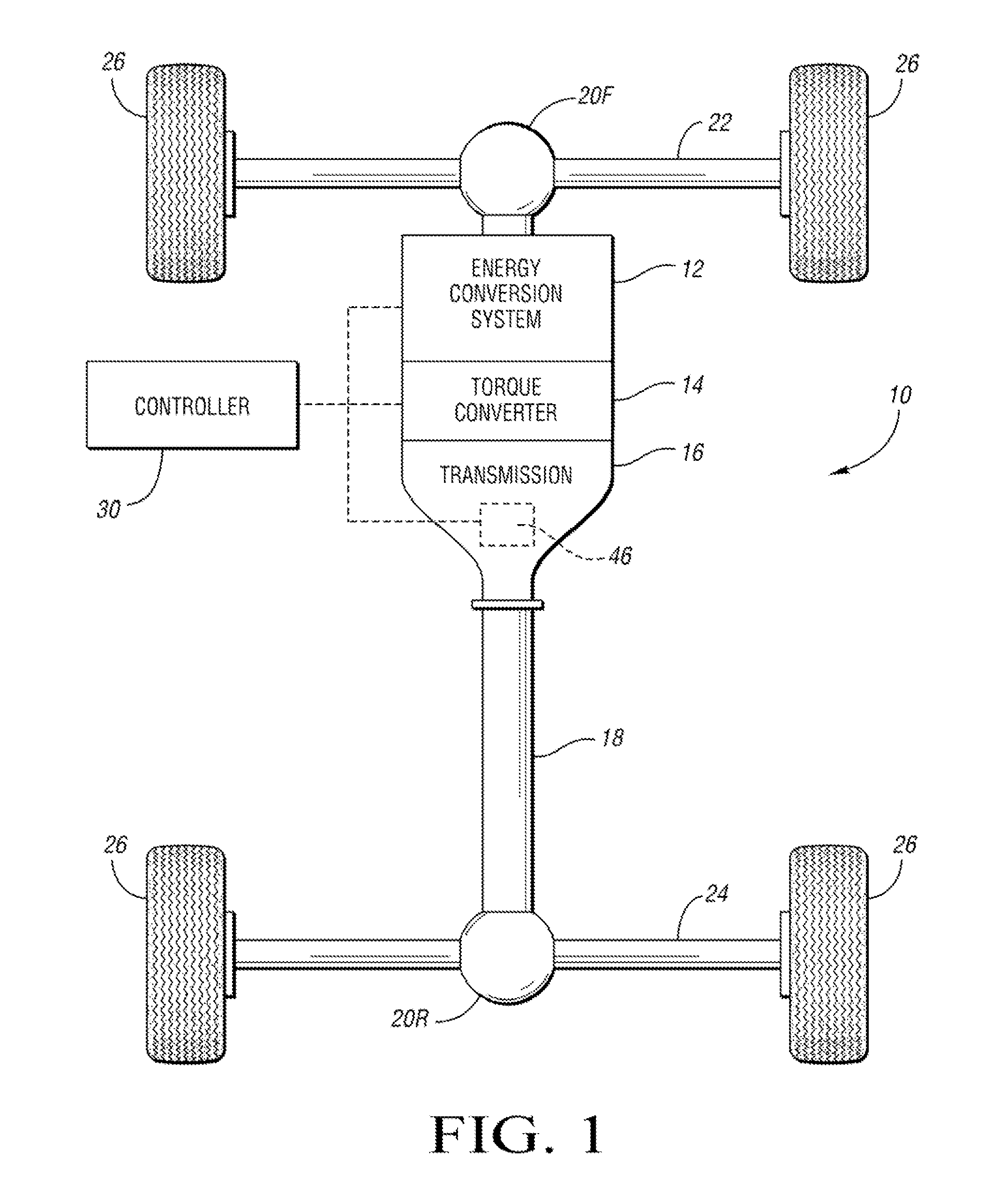
[0013]Referring to the drawings wherein like reference numbers correspond to like or similar components throughout the several figures, there is shown schematically in FIG. 1 a vehicle 10 having a plurality of wheels 26 disposed or positioned on opposing ends of a front axle 22 and a rear axle 24. One or both of the axles 22, 24 are powered or driven by an energy conversion system 12 that is engageable with an automatic power transmission 16 through a hydrodynamic torque converter 14. The energy conversion system 12 is preferably a gasoline or diesel-powered internal combustion engine of the type known in the art, but may also include a fuel cell or other voltage source within the scope of the invention. The transmission 16 has a rotatable input member (not shown) and a rotatable output member 18, and includes a controllable clutch assembly 46 of the invention, which is automatically controllable through a controller 30. The controller 30 may control any or all of energy conversion ...


PUM


Abstract

A clutch assembly is provided for use in a vehicle having an automatic transmission, the assembly including a clutch-apply piston and an integrated one-way clutch, dog clutch apply plate, and synchronizer clutch having a synchronizer plate and a rotating synchronizer cone. The clutch assembly is actuated by a clutch-apply piston configured to axially displace the dog clutch apply plate, thereby engaging the synchronizer plate with the rotating synchronizer cone to synchronize the respective speeds of the synchronizer plate and dog clutch apply plate during a gear shifting event. Upon speed synchronization, continued axial displacement of the clutch-apply piston completes engagement of the dog clutch apply plate to achieve a coast gear state. A return spring provides a return spring force for disengaging the clutch apply piston to permit selection of an alternate gear state during a subsequent gear shifting event.

Description

CROSS REFERENCE TO RELATED APPLICATION[0001]This application claims the benefit of U.S. Provisional Application No. 60 / 823,159, filed Aug. 22, 2006, which is hereby incorporated by reference in its entirety.TECHNICAL FIELD[0002]The present invention relates to a vehicle transmission having a clutch assembly with an integral one-way clutch, synchronizer clutch, and dog clutch apply plate operable for holding a transmission torque capacity during coasting and reverse rotational conditions.BACKGROUND OF THE INVENTION[0003]In a vehicle having an automatic transmission, a rotating-type clutch assembly may be used as a torque-transmitting device for smoothly engaging or coupling a rotating engine crankshaft with a stationary driveshaft to thereby transmit torque from the crankshaft to the vehicle drive wheels. Likewise, the same clutch assembly is used to subsequently disengage the coupled shafts to interrupt the power transfer between the shafts and permit, for example, smooth shifting b...

Claims


Application Information

Patent Timeline
Patent Type & Authority Applications(United States)
IPC IPC(8): F16D23/06
CPCF16D2023/0693F16D23/06
Inventor WITTKOPP, SCOTT H.HART, JAMES M.CAREY, CLINTON E.
Owner GM GLOBAL TECH OPERATIONS LLC
Learn More