Passive Depolarizer

a depolarizer and passive technology, applied in the direction of polarising elements, optical radiation measurement, instruments, etc., can solve the problems of high cost of fabrication of such multi-component devices, measurement errors, and significant errors in polarization sensitivity

Inactive Publication Date: 2008-02-28
JDS UNIPHASE CORP
View PDF30 Cites 22 Cited by
  • Summary
  • Abstract
  • Description
  • Claims
  • Application Information

AI Technical Summary

Problems solved by technology

When such optical elements are used in an optical system, their polarization sensitivity can introduce significant errors.
Therefore, the behavior of the spectrometer will also differ depending on which grating is used, leading to measurement errors.
However, such an ideal depolarizer does not exist.
The fabrication of such multi-component devices is very expensive, limiting their application.

Method used


Image

  • Passive Depolarizer
  • Passive Depolarizer
  • Passive Depolarizer

Examples


Embodiment Construction

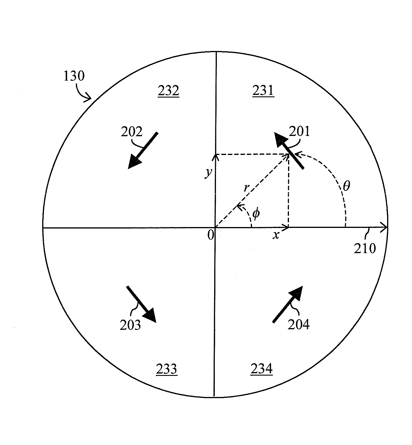
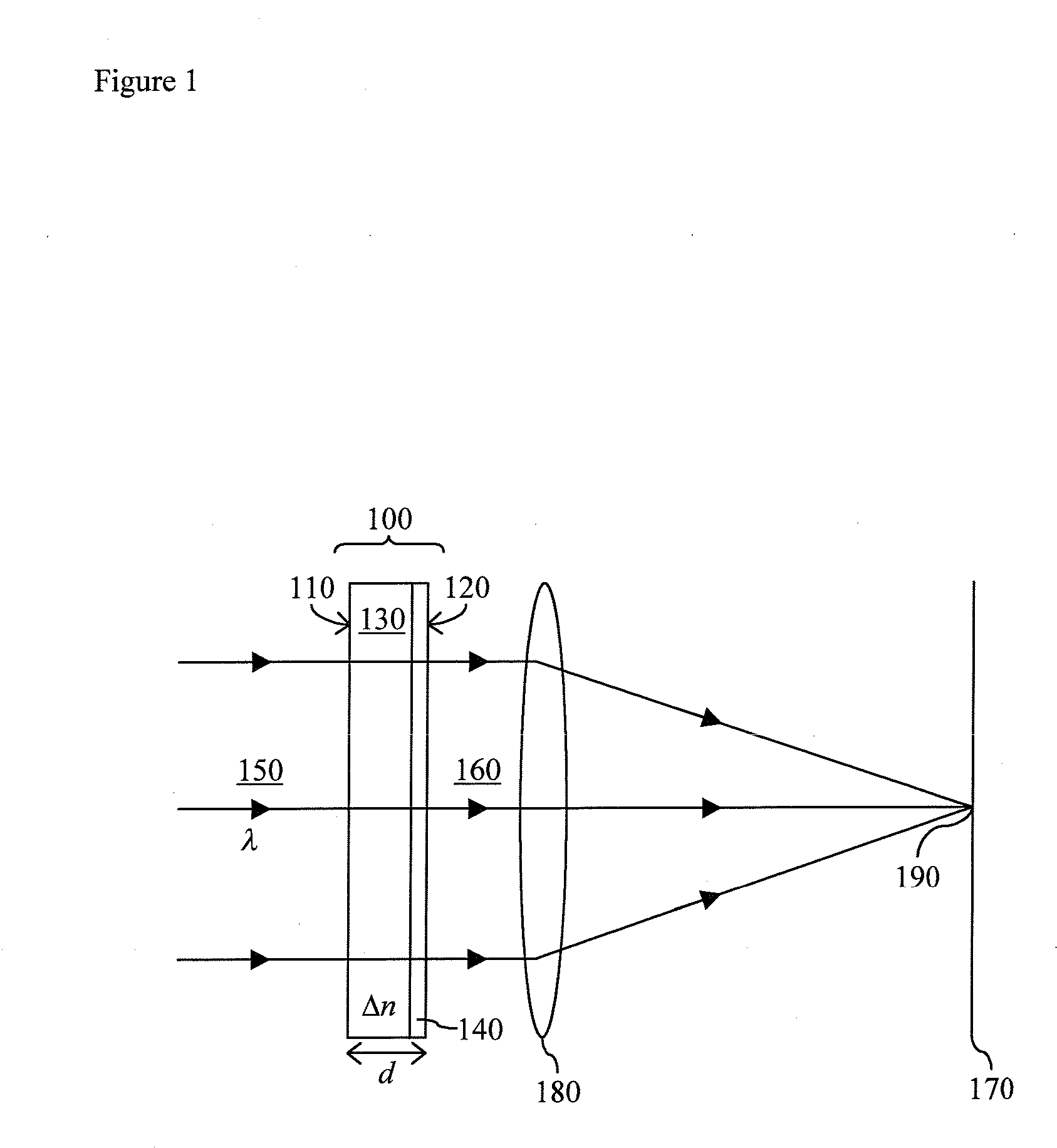
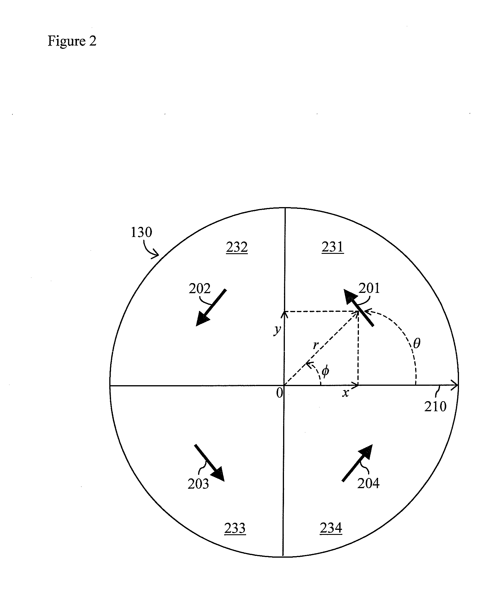
[0022]With reference to FIG. 1, the present invention provides a depolarizer including a patterned half wave plate 100. The patterned half wave plate 100 has an entry surface 110 and an exit surface 120, and includes a monolithic layer 130 of birefringent material. Preferably, the patterned half wave plate 100 may consist of a monolithic layer 130 of birefringent material, or may also include an optional photo-alignment layer 140, which may be adjacent to the entry surface 110 or the exit surface 120.

[0023]The ideal thickness d of the patterned half wave plate 100 may be determined, as described above, on the basis of the average wavelength λ of the incident light beam 150 and the birefringence Δn of the birefringent material of the monolithic layer 130. The incident light beam 150 may be linearly or elliptically polarized and, preferably, has an average wavelength of about 400 to 2000 nm. The birefringent material, preferably, has a birefringence of about 0.05 to 0.5. The actual th...


PUM


Abstract

The present invention relates to a passive depolarizer for use in an optical system having an image plane. The passive depolarizer includes a patterned half wave plate incorporating a monolithic layer of birefringent material. The monolithic layer includes a plurality of regions having fast axes with at least four different orientations. Accordingly, a polarized beam of light launched into the patterned half wave plate is substantially depolarized at the image plane.

Description

CROSS-REFERENCE TO RELATED APPLICATIONS[0001]This application claims priority from U.S. Provisional Application No. 60 / 823,559 filed Aug. 25, 2006, which is hereby incorporated by reference for all purposes.TECHNICAL FIELD[0002]The present invention relates generally to depolarizers and to patterned wave plates. More particularly, the invention relates to a passive depolarizer including a patterned half wave plate.BACKGROUND OF THE INVENTION[0003]Many optical elements are sensitive to the polarization of light. When such optical elements are used in an optical system, their polarization sensitivity can introduce significant errors. To counteract the undesirable effects of polarization sensitivity, a depolarizer can be used to reduce or attempt to randomize the polarization of light.[0004]For instance, typical diffraction gratings used in spectrometers have inherent polarization sensitivity, i.e. their diffraction efficiency depends on the polarization of light. When operating over a...

Claims


Application Information

Patent Timeline
Patent Type & Authority Applications(United States)
IPC IPC(8): G02B5/30
CPCG02B5/3083G01J3/0224
Inventor MCELDOWNEY, SCOTTZIEBA, JERRYNEWELL, MICHAEL
Owner JDS UNIPHASE CORP
Why Eureka
Try Eureka