Current Sensing Load Demand Apparatus and Methods

a current sensing and load technology, applied in the field of electric receptacles, can solve the problems of no special protection, no protection, and no protection at all for afci's, and achieve the effect of preventing all possible circuit faults, ensuring safety, and ensuring safety

Inactive Publication Date: 2008-02-28
TECH MAVERICKS
View PDF3 Cites 36 Cited by
  • Summary
  • Abstract
  • Description
  • Claims
  • Application Information

AI Technical Summary

Benefits of technology

[0012]In one aspect of the present invention, an apparatus for supplying AC power to a load is provided. The apparatus includes a set output terminals, a primary circuit, and a load sensing circuit. The primary circuit is electrically coupled to a source of AC power and to the output terminals for selectively providing power at a low voltage at the output terminals or electronically coupling the source of AC power directly to the output terminals. The load sensing circuit coupled to the primary circuit and the source of AC power for determining a resistance associated with the load at initial application of the load and controlling the primary circuit to electronically couple the source of AC power directly to the output terminals if a proper load is detected.
[0013]In a second aspect of the present invention, an apparatus for supplying AC power to a load is provided. The apparatus includes a primary circuit and a load sensing circuit. The primary circuit is electrically coupled to a source of AC power. The source of AC power has a neutral terminal and a positive terminal. The primary circuit includes a power supply and voltage regulator circuit, a first switch, and a second switch. The power supply and voltage regulator circuit is electrically coupled to the neutral and positive terminals and supplies power at a low voltage. The first switch is coupled to the power supply and voltage regulator circuit, for sensing application of a load and responsively electrically coupling the power supply and voltage regulator circuit to the load. The second switch is electrically coupled between the first switch and the load and having a first position where the first switch and the load are electrically coupled and a second position where the source of AC power is electrically coupled directly to load. The load sensing circuit is coupled to the power supply and voltage regulator circuit for determining a resistance of the load after application of the load and controlling the switch to move to the second position if a proper load is detected.
[0014]In a third aspect of the present invention, a receptacle for supplying AC power to a load is provided. The load has an associated electrical plug. The receptacle includes a set of outlet terminals, an outlet, a primary circuit, and a load sensing circuit. The outlet receives the electrical plug associated with the load. The outlet has at least two associated electrical connectors electrically coupled to the outlet terminals for providing electrical connection to associated prongs of the electrical plug. The primary circuit is electrically coupled to a source of AC power and to the output terminals. The source of AC power has a neutral terminal and a positive terminal. The primary circuit includes a power supply and voltage regulator circuit, which is electrically coupled to the neutral and positive terminals and supplies power at a low voltage, and first and second switches. The first switch is coupled to the power supply and voltage regulator circuit, for sensing insertion of the electrical plug into the outlet and responsively electrically coupling the power supply and voltage regulator circuit to the load. The second switch is electrically coupled between the first switch and the output terminals and has a first position where the first switch and the output terminals are electrically coupled and a second position where the source of AC power is electrically coupled directly to the output terminals. The load sensing circuit is coupled to the power supply and voltage regulator circuit for determining a resistance of the load after insertion of the electrical plug into the outlet and controlling the switch to move to the second position if a proper load is detected.

Problems solved by technology

Arc faults in a home is one of the leading causes for household fires.
Even AFCI's do not, however, provide protection against all of the possible circuit faults that could ignite a fire.
In particular, they provide no special protection against so-called “glow faults” where a relatively low-resistance short circuit draws a modest amount of current (within the trip limits of the circuit breaker) but heats the localized area of the fault to red heat.
Glow faults also can occur where a connection in series with a load suddenly develops a high resistance; this might be the result of a now-defective switch, socket, plug, or wire connection (series faults are observed with special frequency in aluminum wire junctions).
No practical circuit breaker could detect either such fault as there is no measurable characteristic that any circuit breaker could employ to distinguish a glow fault from the normal operation of a branch circuit.
If a short by a conductor is connected between the Neutral and Hot side of a receptacle, the said receptacle will arc, possibly causing fire or electrocution.
Electrical receptacle outlets in walls and floors may present shock and electrical fire hazards to consumers.
Approximately a third of these injuries occur when young children insert metal objects, such as hair pins and keys, into the outlet, resulting in electric shock or burn injuries to the hand or finger.
CPSC also estimates that electric receptacles are involved in 5,300 fires annually which claim 40 lives and injured 110 consumers.
Outlets with poor internal contacts or loose wire terminals may become overheated and emit sparks.
Even a receptacle with nothing plugged into it may run hot if it is passing current through to other outlets on the same circuit.

Method used


Image

  • Current Sensing Load Demand Apparatus and Methods
  • Current Sensing Load Demand Apparatus and Methods
  • Current Sensing Load Demand Apparatus and Methods

Examples


Embodiment Construction

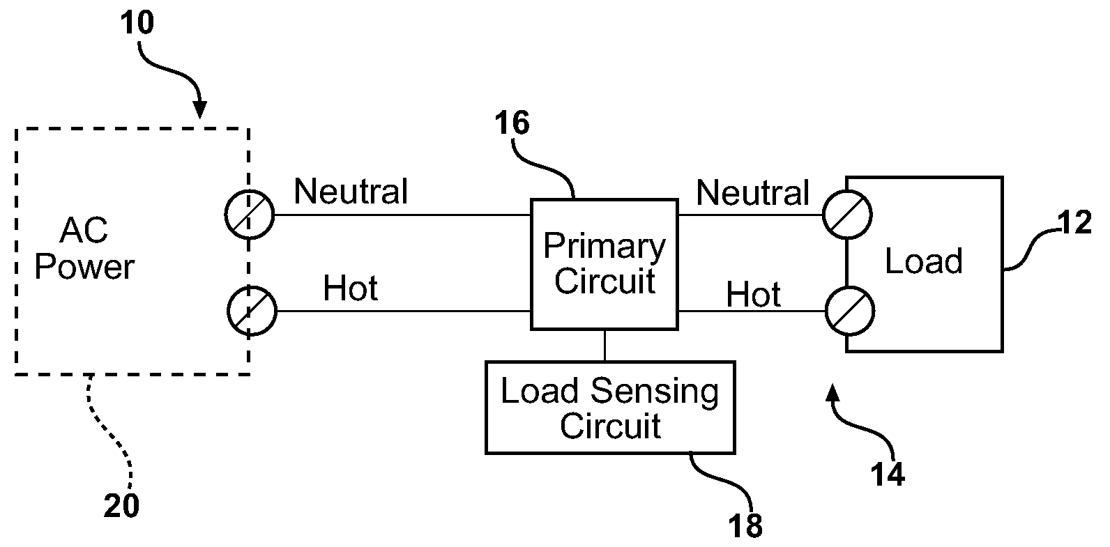
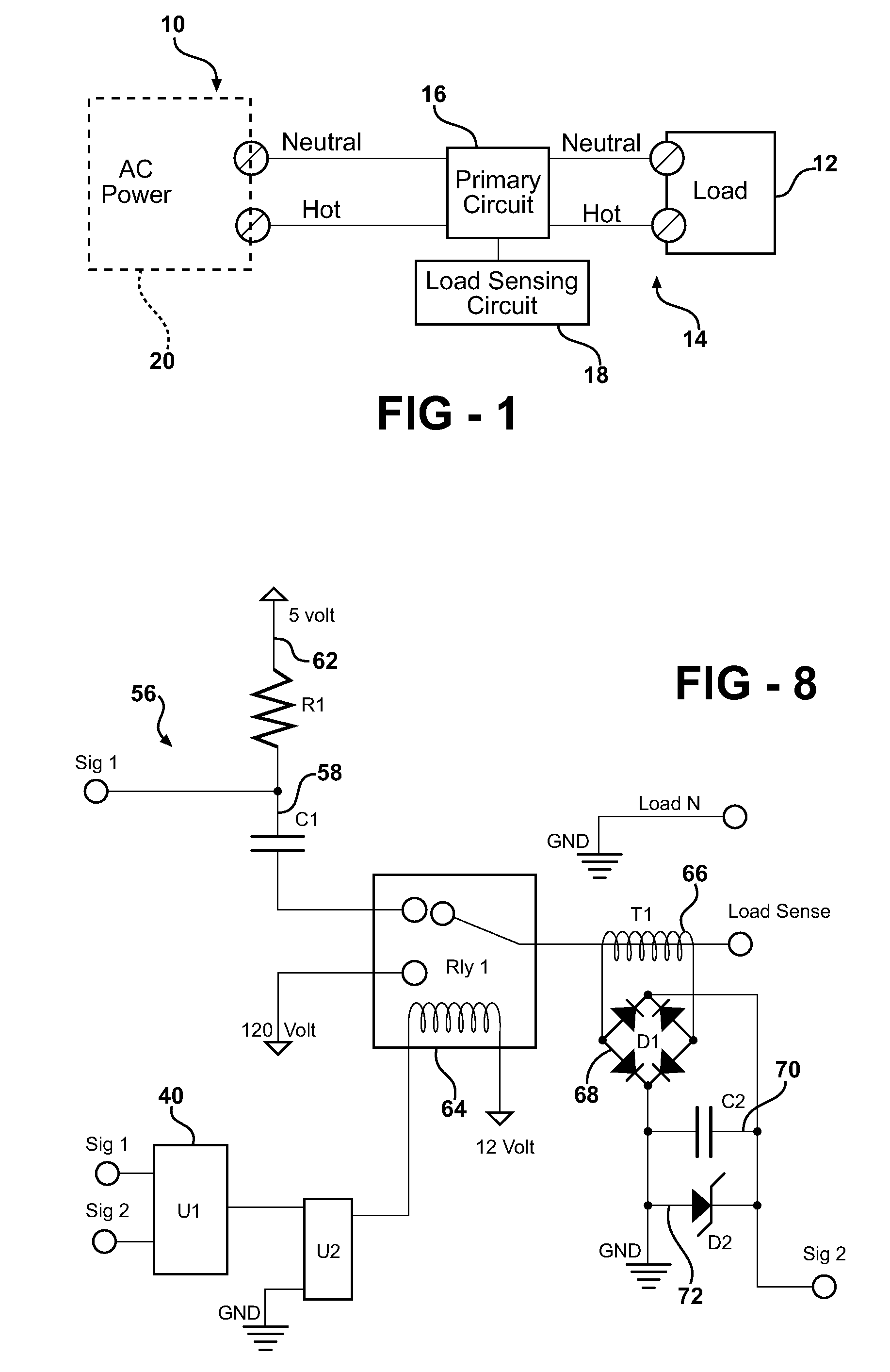
[0028]With reference to the drawings and in operation, the present invention provides an apparatus 10 for supplying AC Power to a load 12.

[0029]With particular reference to FIG. 1, the apparatus 10 includes a pair of output terminals 14, a primary circuit 16, and a load sensing circuit 18. The primary circuit 16 is electrically coupled to a source of AC power 20 and to the output terminals 14. The primary circuit 16 selectively provides power at a low voltage at the output terminals 14 or electronically couples the source of AC power 20 directly to the output terminals 14. In one aspect of the present invention, the primary circuit 16 provides power at the low voltage at the application of the load 12.

[0030]The load sensing circuit 18 is coupled to the primary circuit 16 and the source of AC power 10. The load sensing circuit 18 determines a resistance associated with the load12 at initial application of the load 12 and controls the primary circuit 16 to electronically couple the so...


PUM


Abstract

An apparatus supplies AC power to a load. The apparatus includes a set output terminals, a primary circuit, and a load sensing circuit. The primary circuit is electrically coupled to a source of AC power and to the output terminals for selectively providing power at a low voltage at the output terminals or electronically coupling the source of AC power directly to the output terminals. The load sensing circuit coupled to the primary circuit and the source of AC power for determining a resistance associated with the load at initial application of the load and controlling the primary circuit to electronically couple the source of AC power directly to the output terminals if a proper load is detected.

Description

RELATED APPLICATION[0001]This applications claims priority to U.S. Provisional Patent Application Ser. No. 60 / 823,455, filed Aug. 24, 2006, the entire specification of which is hereby expressly incorporated by reference.FIELD OF THE INVENTION[0002]This description relates generally to electrical receptacles and more particularly to a method of load verification of an electrical current demand, which ensures such demand does not exceed the operational parameters of said receptacles.BACKGROUND[0003]Conventional electrical receptacles used in industrial, commercial and residential applications deliver electricity to a variety of electrical appliances. The receptacles manufactured today have a hard Lexan plastic enclosure and deliver a hot, neutral and ground to said electrical appliances via a plug which is inserted into three of the six holes in a typical grounded application. Voltage and current travel through the hot conductor to the appliance circuit. If the appliance circuit is sw...

Claims


Application Information

Patent Timeline
Patent Type & Authority Applications(United States)
IPC IPC(8): H02H3/00H02H3/04
CPCH02H3/12
Inventor CARSON, ANTHONYNOLAND, BRYAN
Owner TECH MAVERICKS
Why Eureka
Try Eureka