Expansion dowel

Inactive Publication Date: 2008-02-28
HILTI AG
19 Cites 40 Cited by

AI-Extracted Technical Summary

Problems solved by technology

In practice, however, often higher torques than predetermined ones are applied to an expansion dowel because, in most cases, torque wrenches are not used for anchoring an expansion dowel in a constructional component.
The possibility of using higher, than predetermined torques requires that the axis and edge distances be determined with a corresponding reliability with respect to the torque, otherwise a technical potential of an expansion dowel cannot be completely utilized.
Further, in an extreme case, the expansion part can be pulled through the expansion sleeve which would result in a comp...

Benefits of technology

[0020] Advantageously, the elevations of the profile are oriented in the direction of the first end region of the anchor bolt. Because of this orientation, the increase of the friction upon an increased axial advance of the expansion sleeve, c...

Abstract

An expansion dowel includes an anchor bolt (12) having a load application element (16) at a first end region (14) of the anchor bolt (12), and an expansion part (17) at a second free end region (15) of the anchor bolt (12), and an expansion sleeve (21) having an inner profile (22) with a region (23) having a surface roughness increasing in the direction of the first end region (14) of the anchor bolt (12), with the expansion part (17) having a conical section (18) widening toward the second free end region (15) of the anchor bolt (12) for expanding the expansion sleeve (18).

Application Domain

Technology Topic

Image

  • Expansion dowel
  • Expansion dowel
  • Expansion dowel

Examples

  • Experimental program(1)

Example

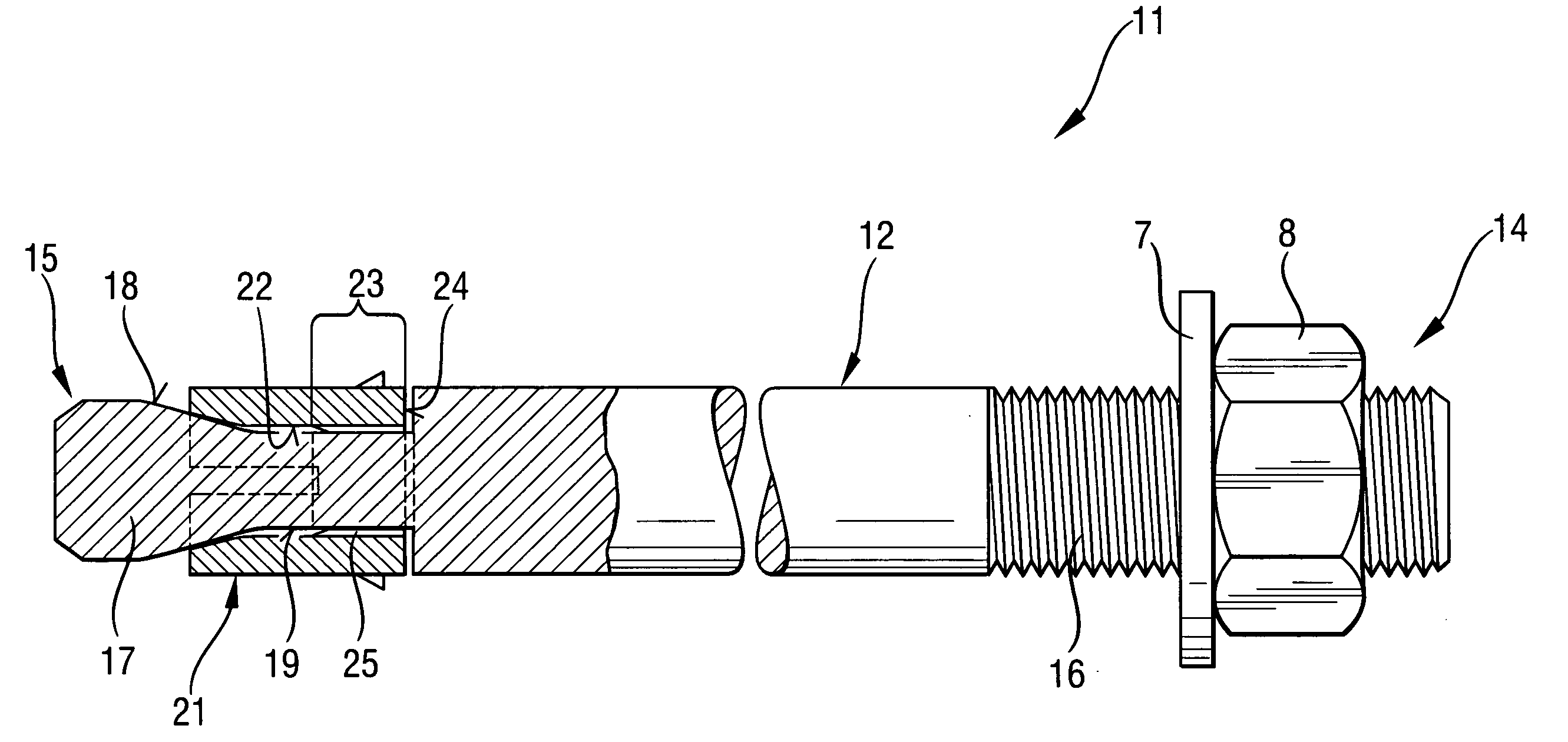
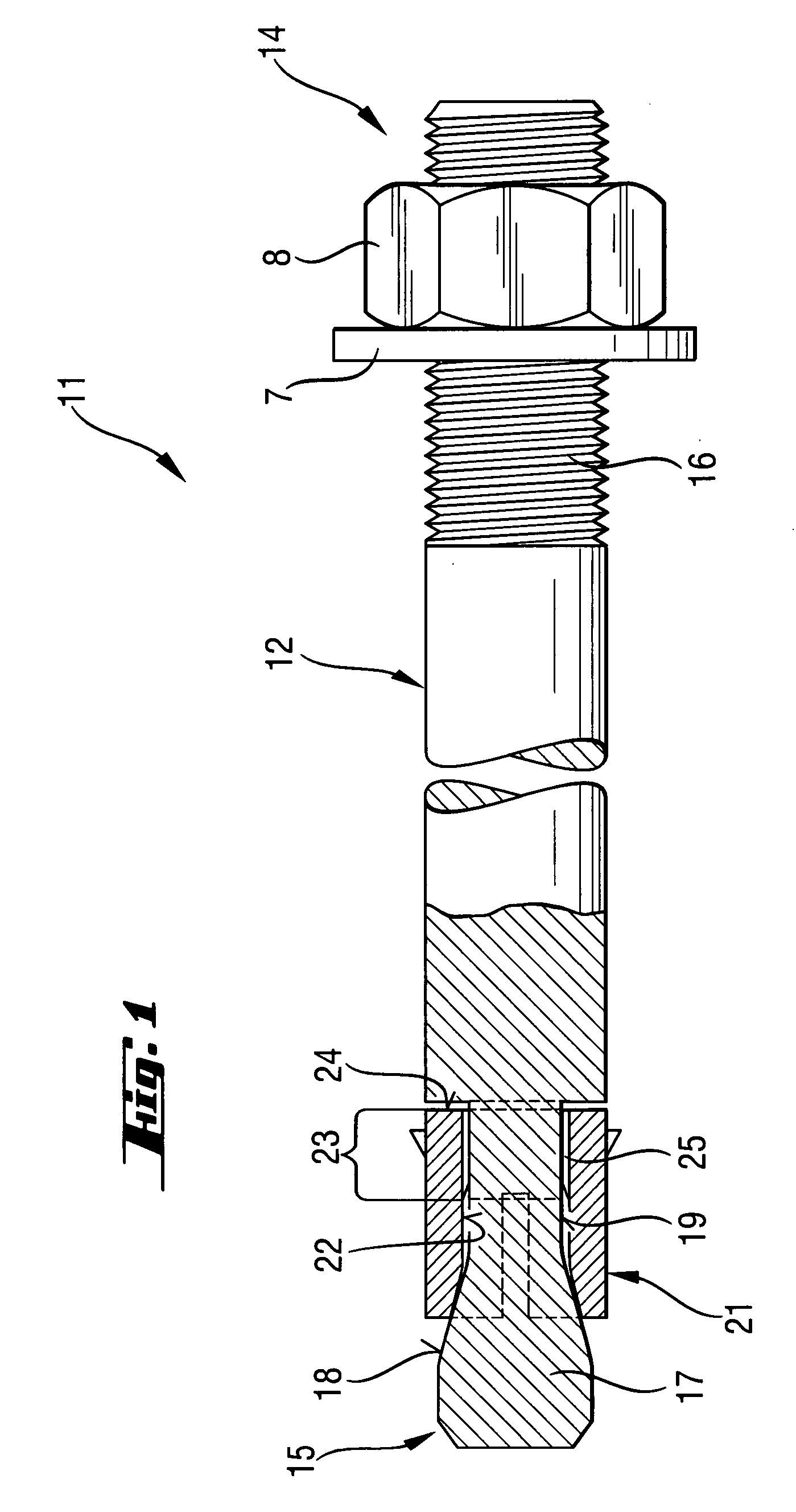
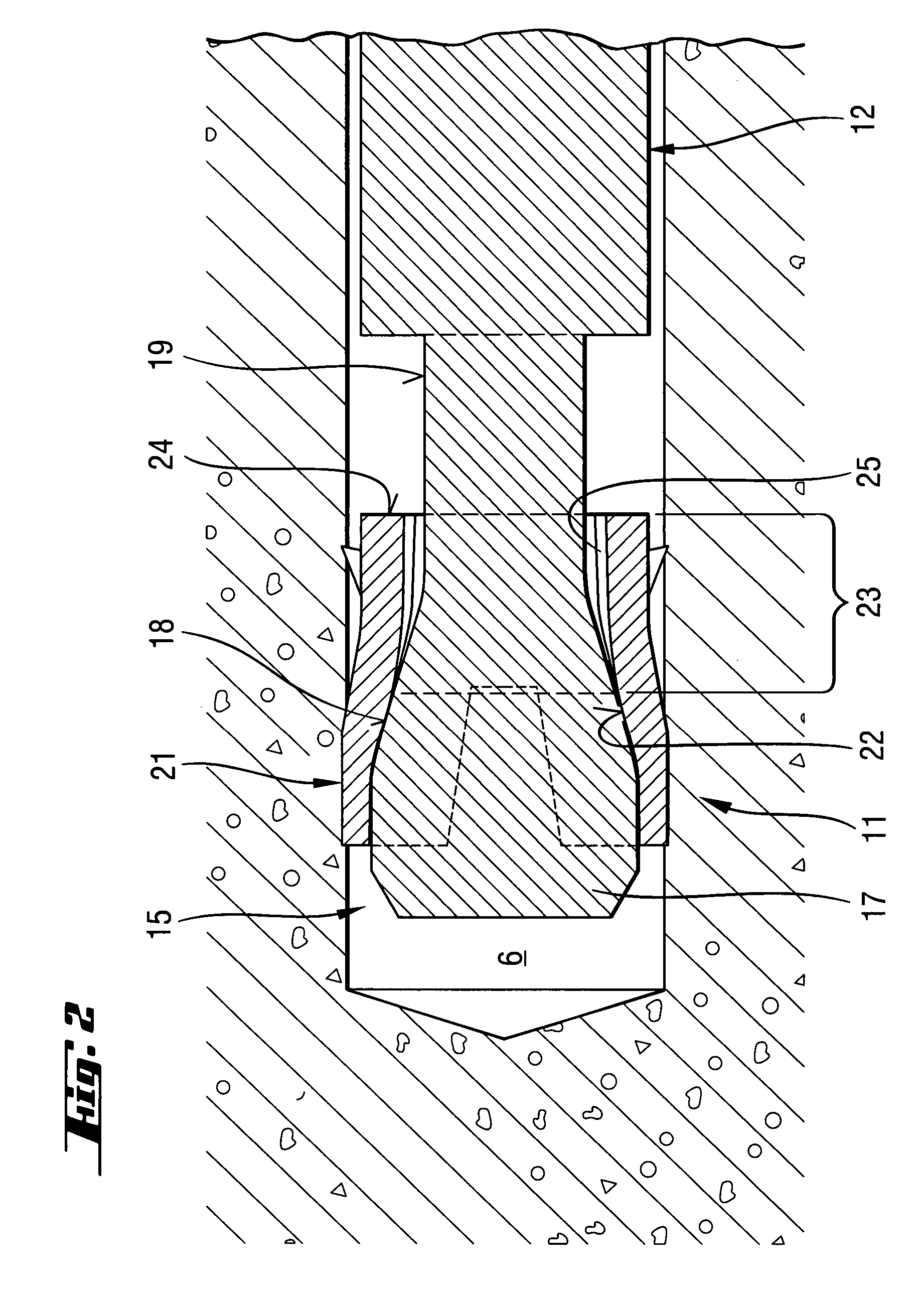
[0025] An expansion dowel 11 according to the present invention, which is shown in the drawings, has an anchor bolt 12 and an expansion sleeve 21. At its first end region 14, the anchor bolt 12 has a threaded section that serves as load application means 16. At its second end region 15, the anchor bolt 12 is provided with an expansion part 17 for expanding the expansion sleeve 21. In the embodiment shown in the drawings, the expansion part 17 is formed integrally with the anchor bolt 12. The expansion part 17 has a conical section 18 that widens in the direction of the free end of the second end region 15 of the anchor bolt 12. On the anchor bolt 12, there is provided a neck 19 in which the expansion sleeve 21 is arranged.
[0026] The expansion sleeve 21 has, on its inner profile 22, a region 23 having an increasing surface roughness and bringable in abutment with the expansion part 17. The region 23 extends from an end 24 of the expansion sleeve 21 adjacent to the first end region 14 of the anchor bolt 12 and in the direction of the free end of the second end region 15 of the anchor bolt 12. The increasing surface roughness is formed by a profile 25 having an increasing height in the direction of the first region 14 of the anchor bolt 15. The elevations of the profile 25, which project beyond the inner generatrix of the expansion sleeve 21, run in the direction of the first end region 14 of the anchor bolt 12 parallel to the anchor bolt 12.
[0027] The expansion dowel 11 is driven in a preliminary formed borehole 6 and is locked, e.g., with a nut 8 that engages a washer 7. Upon further rotation of the nut 8, the anchor bolt 12 is displaced axially into the expansion sleeve 21 that becomes clamped between the expansion part 17 of the anchor bolt 12 and the wall of the borehole 6. As a result, the region 23 which has, as it has already been discussed above, an increasing surface roughness, comes in abutment with the conical section 18 of the expansion part 17. Thereby, upon a farther application of a torque, the frictional resistance between the expansion sleeve 21 and the expansion part 17 of the anchor bolt 12 also progressively increases.
[0028] Though the present invention was shown and described with references to the preferred embodiment, such are merely illustrative of the present invention and are not to be construed as a limitation thereof and various modifications of the present invention will be apparent to those skilled in the art. It is, therefore, not intended that the present invention be limited to the disclosed embodiment or details thereof, and the present invention includes all variations and/or alternative embodiments within the spirit and scope of the present invention as defined by the appended claims.

PUM

no PUM

Description & Claims & Application Information

We can also present the details of the Description, Claims and Application information to help users get a comprehensive understanding of the technical details of the patent, such as background art, summary of invention, brief description of drawings, description of embodiments, and other original content. On the other hand, users can also determine the specific scope of protection of the technology through the list of claims; as well as understand the changes in the life cycle of the technology with the presentation of the patent timeline. Login to view more.

Similar technology patents

Classification and recommendation of technical efficacy words

  • Increase friction
  • Well control

Cord anchor

InactiveUS20070023149A1Increase frictionExtensible doors/windowsCurtain accessoriesWindow coveringEngineering
Owner:HUNTER DOUGLAS IND BV

Lead obstacle-crossing robot walking device

ActiveCN101574983AIncrease frictionIncrease crawl angleManipulatorCable installation apparatusHigh voltage transmission linesEngineering
Owner:CHINA ELECTRIC POWER RES INST +1

Apparatus for catalytic distillation

InactiveUS6045762AUniform applicationWell controlCarburetting airUsing liquid separation agentCatalytic distillationMass transfer
Owner:THE UNIV OF ALBERTA

Instrument for measuring dimensions and height gauge

ActiveUS20100287786A1Increase elastic displacement limitWell controlFeeler-pin gaugesMechanical measuring arrangementsLinear displacementElectricity
Owner:TESA SE

Liquid ejection device

InactiveUS20110221843A1Reduce extentWell controlOther printing apparatusEngineering
Owner:SEIKO EPSON CORP

Fast single phase program algorithm for quadbit

ActiveUS20090103357A1Well controlMaintain controlRead-only memoriesDigital storageSingle phaseProgramming patterns
Owner:INFINEON TECH LLC

Process for resurf diffusion for high voltage MOSFET

ActiveUS20060006555A1Good distribution and controlWell controlSemiconductor/solid-state device detailsSolid-state devicesArsenicP type silicon
Owner:INFINEON TECH AMERICAS

People also interested in

Why Eureka
Try Eureka