Fastening element for hard constructional component

Inactive Publication Date: 2008-02-28
HILTI AG
View PDF17 Cites 8 Cited by
  • Summary
  • Abstract
  • Description
  • Claims
  • Application Information

AI Technical Summary

Benefits of technology

[0019] The fastening element according to the present invention can be set easily and with comparatively small force. Moreover, the inventive fastening element can be set in a previously formed borehole without the use of the hardenable mass, because a small annular gap between the outer surface of the base body and the borehole wall insures a good anchoring of the fastening element in the constructional component.
[0020] The at least one groove can be formed in the base body during rolling or with a separate manufacturing process, e.g., by machining, which enables a cost-effective manufacturing of the fastening element.
[0021] Preferably, the at least one groove extends, at least regionwise, parallel to the thread. The groove runs essentially in form of a spiral w

Problems solved by technology

The drawback of the fastening element of U.S. Pat. No. 4,350,464 consists in that the size of the annular gap between the outer surface of the base body and the borehole wall from an attachment point to an attachment point can vary greatly, dependent on the properties of the constructional component and type and condition of the tool for forming the borehole.
In addition, high loads can act on undercuts in the constructional component which are produced by the thread.
These loads can lead to a partial or, in the extreme case, to a complete failure of the formed attachment point.
In order to prevent this and to achieve a high load-carrying capacity, such fastening elem

Method used


Image

  • Fastening element for hard constructional component
  • Fastening element for hard constructional component
  • Fastening element for hard constructional component

Examples


Example

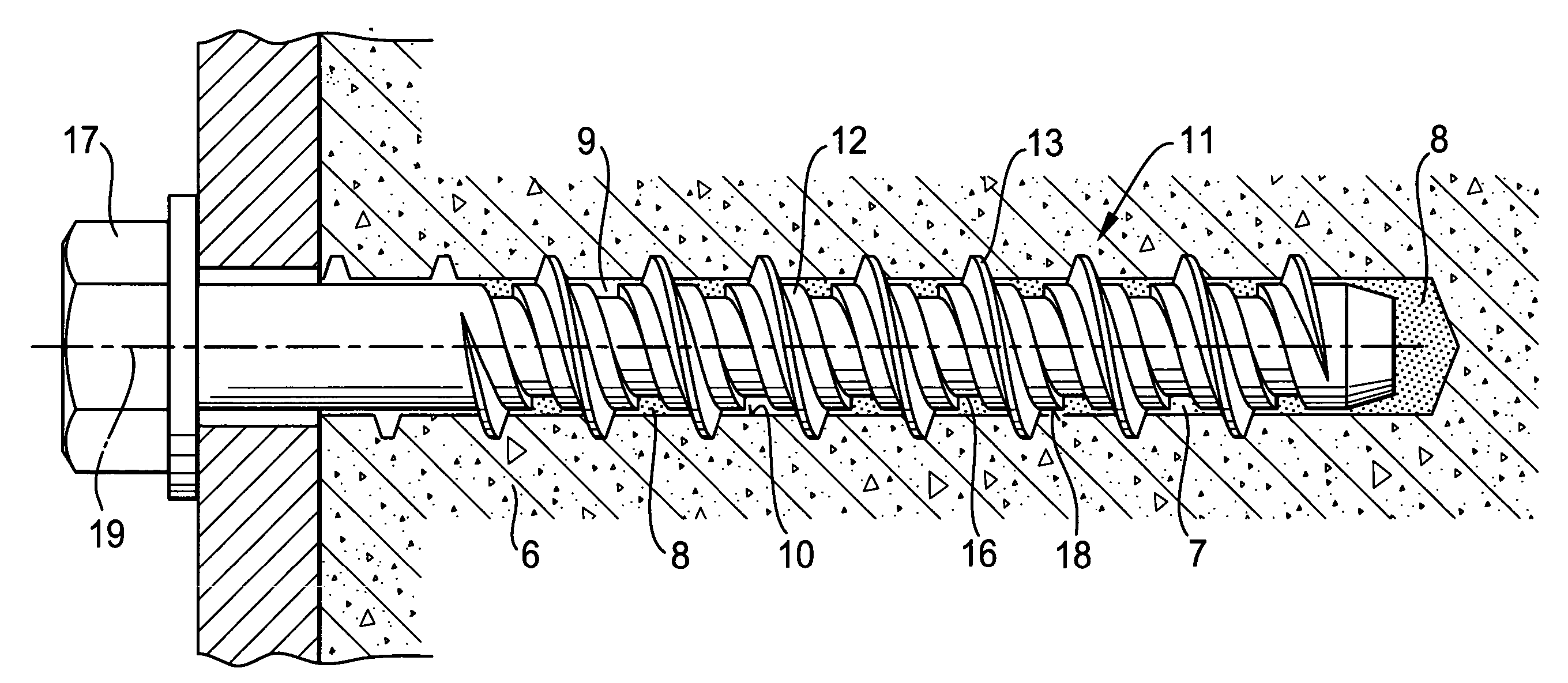
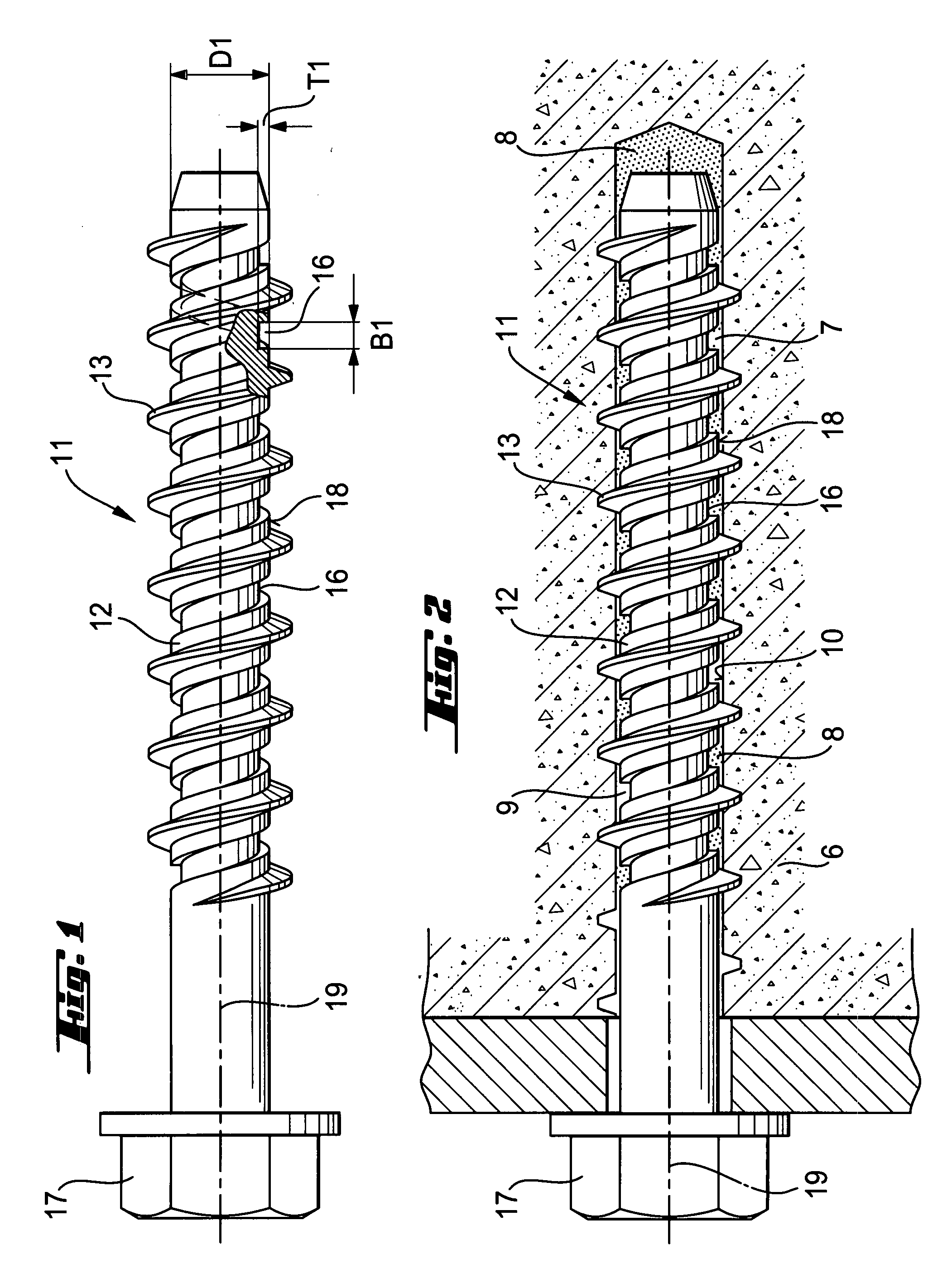
[0039] A fastening element 11 according to the present invention which is designed for use in a hard constructional component 6 such as concrete masonry and the like and which is shown in FIGS. 1-2, is formed as a concrete screw set in a borehole 7 formed in the constructional component. The fastening element 11 has a shaft that forms a base body 12 extending along a longitudinal axis 19. The base body 12 has an outer surface 18 and a hexagonal head 17 that serves as engagement means for a setting tool not shown. The fastening element 11 is set percussively and / or rotationally. On the base body 12, there is provided a self-tapping thread 13 the height of which extends radially outwardly from the outer surface 18 of the base body 12.

[0040] On the base body 12, there is further provided a groove 16 for a hardenable mass 8 and which extends parallel to the thread 13 between the separate threads and axially spaced from the threads. The groove 16 has a depth T1 that corresponds to one / t...


PUM


Abstract

A fastening element for a hard constructional component (6) includes a base body (12; 22; 42) extending along a longitudinal axis (19; 29; 49), a self-tapping thread (13; 23; 43) provided, at least regionwise, on the base body (12; 22; 42) and a height of which extends radially outwardly from the outer surface (18, 28, 48) of the base body (12; 22; 42), and at least one groove (16, 26, 45, 46, 47) provided on the base body (12; 22; 42) and a depth (T1, T2) of which extends radially inwardly from the outer surface (18; 28; 48) of the base body (12; 22; 42) and which is axially spaced from the self-tapping thread (13; 23; 43).

Description

BACKGROUND OF THE INVENTION [0001] 1. Field of the Invention [0002] The present invention relates to a fastening element for a hard constructional component and including a base body extending along a longitudinal axis and having an outer surface, a self-tapping thread provided, at least regionwise, on the base body and a height of which extends radially outwardly from the outer surface of the base body. At least one groove provided on the base body and a depth of which extends radially inwardly from the outer surface of the base body. [0003] 2. Description of the Prior Art [0004] Different types of fastening elements for hard constructional components such as concrete, masonry and the like are known fastening elements are set in preliminary formed boreholes in a constructional component percussively and / or rotary, dependent on their shape. [0005] European Patent EP 0 623 759 B1 discloses a thread-forming screw for being screwed in a hard constructional component and having a shaft ...

Claims


Application Information

Patent Timeline
IPC IPC(8): F16B25/00
CPCF16B5/0275F16B13/002F16B13/141F16B25/10F16B25/0068F16B25/0078F16B25/0026
Inventor AYRLE, THOMSSCHAEFFER, MARC
Owner HILTI AG
Why Eureka
Try Eureka