Card connector

a card connector and card slot technology, applied in the direction of coupling device connection, conveying record carriers, instruments, etc., can solve the problems of memory cards having the image of low memory capacity, high cost, and consuming very little electrical power for reading and writing data,

Inactive Publication Date: 2008-02-28
JST MFG CO LTD
View PDF3 Cites 18 Cited by
  • Summary
  • Abstract
  • Description
  • Claims
  • Application Information

AI Technical Summary

Benefits of technology

[0054]The card connector of the present invention securely prevents a card from unexpectedly being ejected and securely maintains the card mounting state by way of a leaf spring having a semi-circular claw being equipped at a sliding member, and the semi-circular claw mating with a square concave portion formed in the card.

Problems solved by technology

The memory card is extremely compact and consumes very little electrical power in reading and writing data.
In the past, memory cards had the image of having low memory capacity, yet higher costs, compared to other disk-shaped memory devices such as flexible disks (FD) and magnetic optical disks (MO).
However, technical advancements made in recent years, and the effects of mass production accompanying popularization of devices that use memory cards, has pushed memory capacity to more than 128 MB, and driven down costs.
Since the card 9c is biased by a rubber body in the card connector disclosed in Patent Document 2, there is a durability problem to wear caused by repeated use.
Furthermore, with the card 9c mounted, because the card is held by only the pressing force of a plurality of contacts 93 (see FIG. 11), there is the danger of the card being moved by vibrations, or the like.
This can also be a cause of improper contact between the card 9c and the contact 93.

Method used


Image

  • Card connector
  • Card connector
  • Card connector

Examples


Embodiment Construction

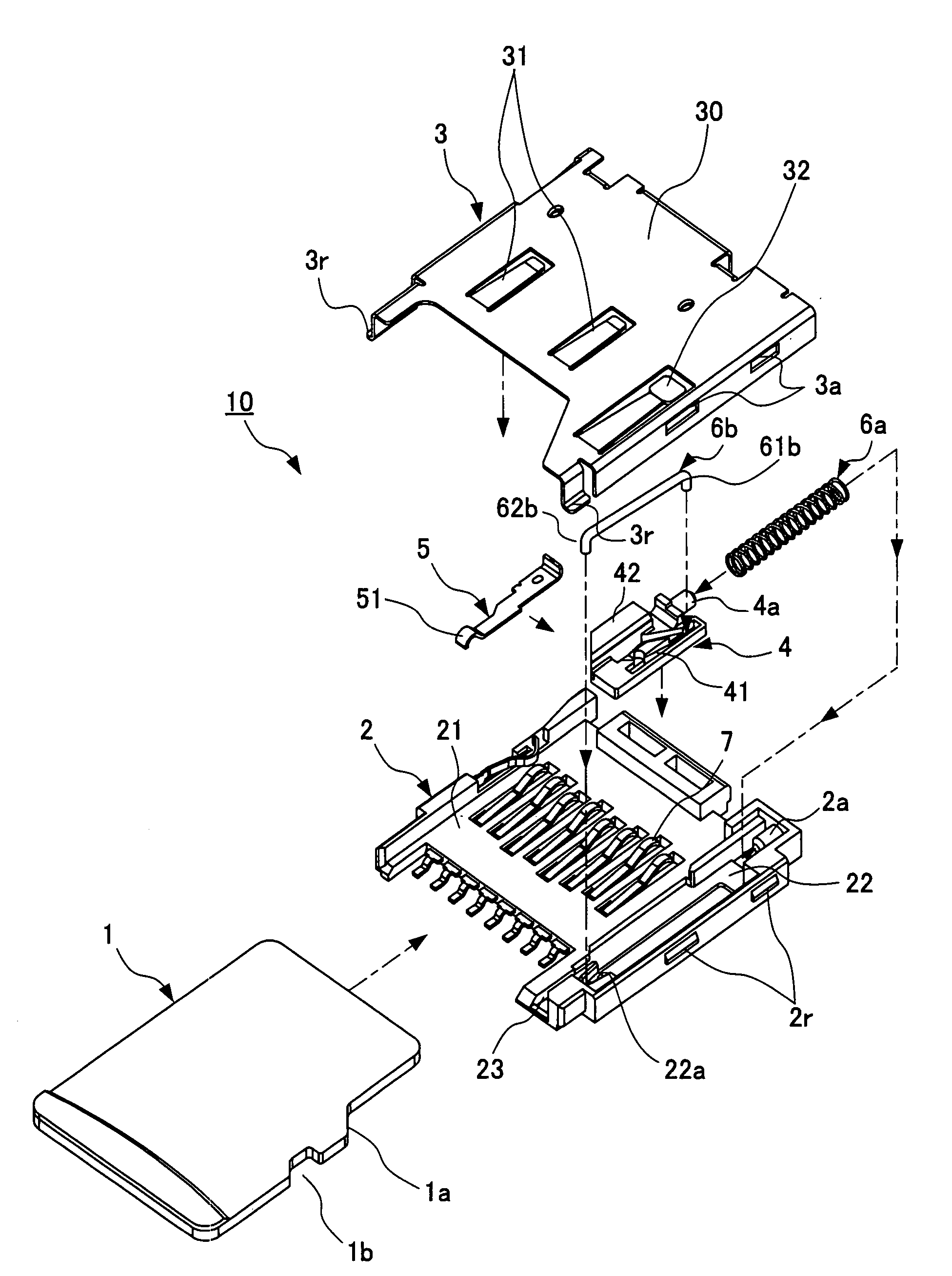
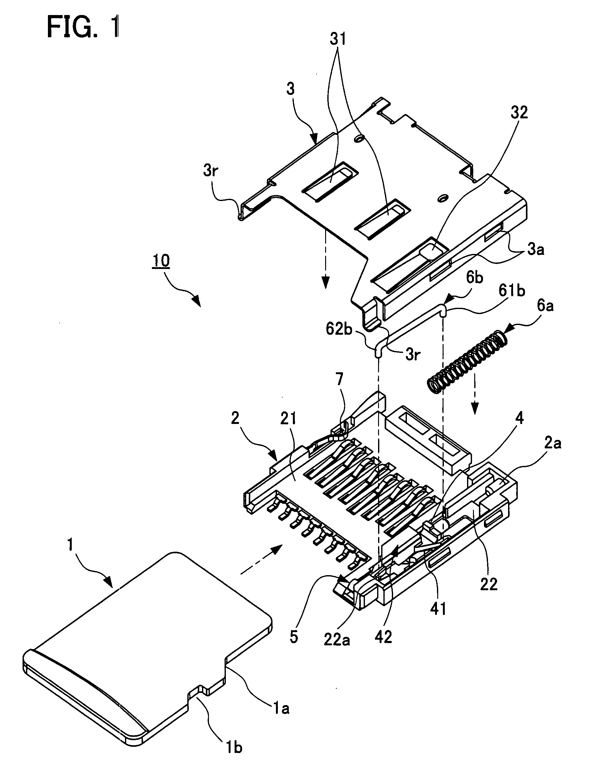
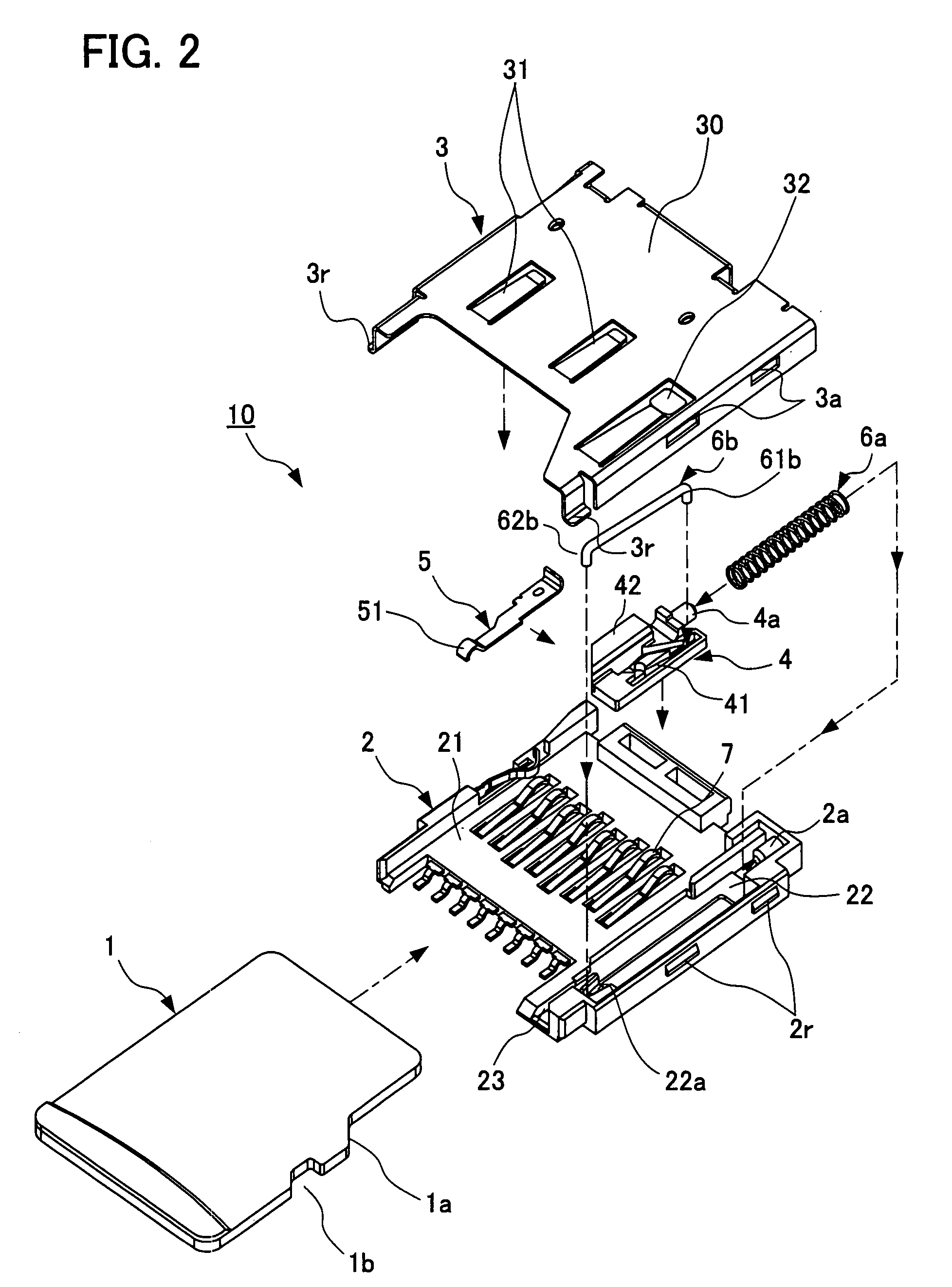
[0066]FIG. 1 is an exploded perspective view of one embodiment of the card connector (hereinafter referred to simply as a connector) according to the present invention. FIG. 2 is an exploded perspective view of the connector according to the embodiment. FIG. 3 is a perspective outline view of the connector according to the embodiment, and shows the cover removed. FIG. 4 is a perspective outline view of the connector according to the embodiment, and shows the cover mounted.

[0067]FIG. 5 is a plan view of the connector according to the embodiment. FIG. 6 is a perspective outline view of the connector according to the embodiment, showing the connector from a direction different from FIG. 3. FIG. 7 is a side view of the sliding member of the connector according to the embodiment. FIG. 8 is an expanded perspective outline view of an essential portion of the connector according to the embodiment. FIG. 9 is an expanded perspective outline view of the essential portion of the connector accor...


PUM


Abstract

A sliding member is disposed on one wing of the concave portion to advance and retreat in directions parallel to insertion and ejection of a card, and formed a heart-shaped cam groove. The base-end side of the leaf spring is fastened to the sliding member; the other end projects toward the opening of the concave portion. A compressed-coil spring applies a biasing force on the sliding member in a direction of card ejection. One end of the guide rod is coupled to the heart-shaped cam groove; the other end is pivotably supported on the housing. The sliding member has an engaging piece that touches an oblique side formed on a side surface of the card, and the leaf spring has a semi-circular claw that moves in and out of a surface of the card at a substantially square concave portion, thereby resiliently engaging the concave portion.

Description

[0001]This application is based on and claims the benefit of priority from Japanese Patent Application No. 2006-229793, filed on 25 Aug. 2006, the content of which is incorporated herein by reference.BACKGROUND OF THE INVENTION[0002]1. Field of the Invention[0003]The present invention relates to card connectors. Particularly, the present invention relates to manufacturing card connectors that electrically connect to a miniature memory card such as a micro SD (Secure Digital) card being inserted into the connector.[0004]2. Related Art[0005]A memory card, which is a card-shaped memory device, employs flash memory as a memory medium. The memory card is extremely compact and consumes very little electrical power in reading and writing data. For these reasons, memory cards have become popular as a memory medium for hand-held information devices, as represented, for example, by camera-cellphones and PDAs (Personal Digital Assistant).[0006]In the past, memory cards had the image of having ...

Claims


Application Information

Patent Timeline
Patent Type & Authority Applications(United States)
IPC IPC(8): H01R12/16H01R13/62
CPCG06K13/0806G06K13/08
Inventor MIYAO, TAICHIROASAOKA, NORIHIROYAMADA, HIDEYASU
Owner JST MFG CO LTD
Why Eureka
Try Eureka