Network switching device and control method of network switching device

a network switching and control method technology, applied in data switching networks, memory adressing/allocation/relocation, instruments, etc., can solve the problems of undesirable increase in the processing load of each of the multiple switching processors, and achieve the effect of efficient standardization of the contents of the respective address tabl

Inactive Publication Date: 2008-02-28
ALAXALA NETWORKS
View PDF10 Cites 117 Cited by
  • Summary
  • Abstract
  • Description
  • Claims
  • Application Information

AI Technical Summary

Benefits of technology

[0008]An advantage of some aspects of the invention is, in a network switching device having multiple switching processors respectively storing address tables, to efficiently standardize the contents of the respective address tables.

Problems solved by technology

This may undesirably increase the processing load in each of the multiple switching processors.

Method used


Image

  • Network switching device and control method of network switching device
  • Network switching device and control method of network switching device
  • Network switching device and control method of network switching device

Examples


first embodiment

A. First Embodiment

[0034]Configuration of Network Switching Device

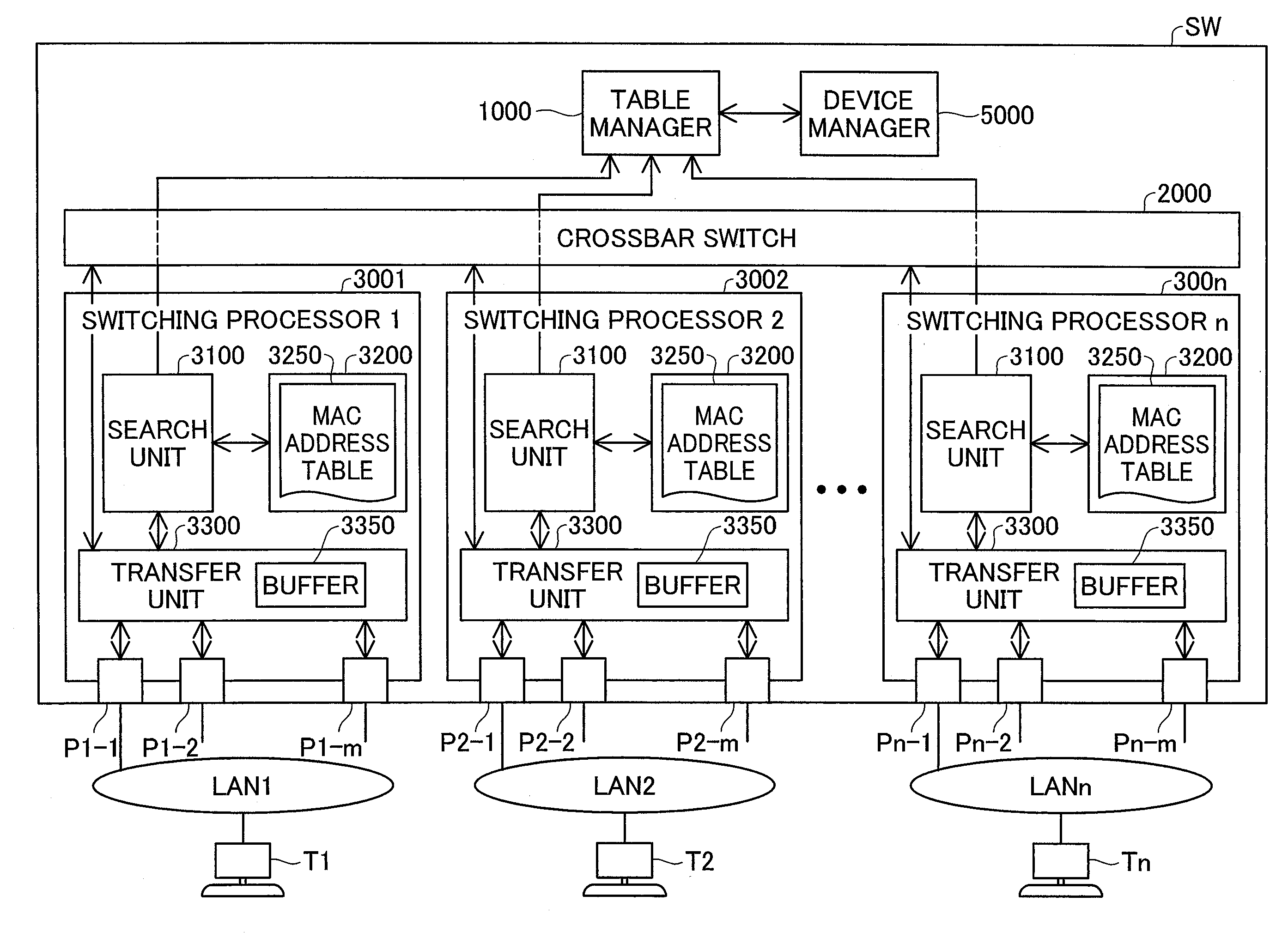
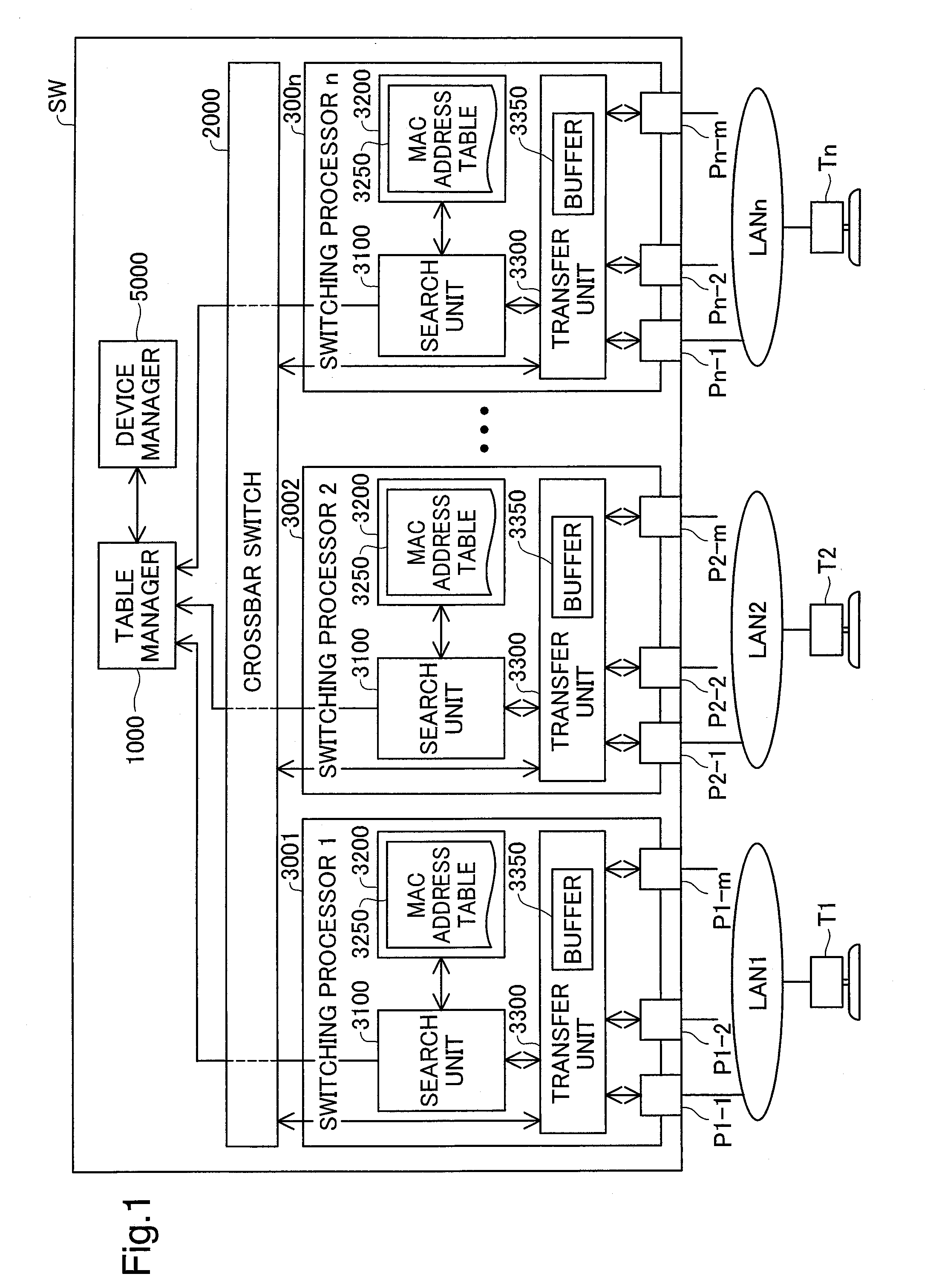
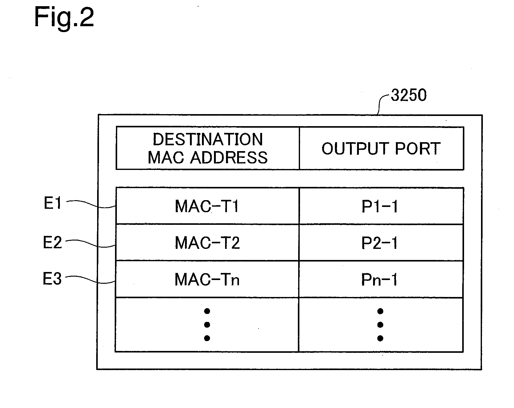
[0035]Some modes of carrying out the invention are described below as preferred embodiments with reference to the accompanied drawings. The description first regards the configuration of a network switching device SW in a first embodiment of the invention with reference to FIGS. 1 through 4. FIG. 1 is a block diagram schematically illustrating the structure of the network switching device SW in the first embodiment. FIG. 2 shows one example of a MAC address table 3250 adopted in the network switching device SW. FIG. 3 is a block diagram showing the internal structure of a search unit 3100 included in the network switching device SW of FIG. 1. FIG. 4 is a block diagram showing the internal structure of a table manager 1000 included in the network switching device SW of FIG. 1.

[0036]As shown in FIG. 1, a network switching device SW of the first embodiment includes a table manager 1000, a crossbar switch 2000, multiple s...

second embodiment

B. Second Embodiment

[0080]The configuration of a network switching device SWa in a second embodiment of the invention is described with reference to FIG. 10. FIG. 10 is a block diagram schematically illustrating the structure of the network switching device SWa in the second embodiment. In the network switching device SW of the first embodiment, the multiple switching processors 3001 through 300n are mutually connected via the crossbar switch 2000. In the network switching device SWa of the second embodiment, however, the multiple switching processors 3001 through 300n are not mutually connected. In the network switching device SW of the first embodiment, each of the multiple ports is connected to the transfer unit 3300 in one of the multiple switching processors 3001 through 300n. The network switching device SWa of the second embodiment has multiple frame sending and receiving units 5001 through 500n. Each of the multiple ports is connected to one of the multiple frame sending and...


PUM


Abstract

A network switching device includes multiple ports, multiple switching processors, and a table manager. The switching processors respectively have an address table, a output port specification module, an update requirement determination module, and a table update module. The output port specification module refers to a destination address in received data and the address table and specifies a output port for sending the data among the multiple ports. The update requirement determination module determines requirement for update of the address table with regard to a source address in the data. The table manager has an update detail acquisition module and an update request module. Upon determination of the requirement for update of the address table, the update detail acquisition module obtains an update detail of the address table from one of the switching processors. The update request module sends an update request to the switching processors, based on the update detail.

Description

CROSS REFERENCE TO RELATED APPLICATIONS[0001]This application relates to and claims priority from Japanese Patent Applications No. 2006-229028, filed on Aug. 31, 2006, the entire disclosure of which is incorporated by reference.BACKGROUND[0002]1. Technical Field[0003]The present invention relates to a network switching device and a control method of the network switching device.[0004]2. Description of the Related Art[0005]A conventionally used network switching device (for example, a layer 2 switch) relays data, based on a destination address such as MAC address related to the data. The network switching device has multiple switching processors, which individually store address tables and specify a output port of the data based on the destination address. The network switching device requires a management system for standardizing the contents of the respective address tables.[0006]In a prior art network switching device adopting a proposed technique, each of multiple switching proce...

Claims


Application Information

Patent Timeline
Patent Type & Authority Applications(United States)
IPC IPC(8): G06F12/02H04L12/28
CPCH04L49/309H04L49/101
Inventor AKAHANE, SHINICHINAGASAKA, MITSURUYANO, HIROKITAKAGI, YUTAKA
Owner ALAXALA NETWORKS
Why Eureka
Try Eureka