Fault detection unit for rotation angle detecting device

a technology of fault detection and detection device, which is applied in the direction of instruments, nuclear elements, nuclear engineering, etc., can solve the problems of erroneously judged that no the unit cannot temporarily detect the amplitude signals correctly, and the error of judging that a fault has occurred in the resolver

Inactive Publication Date: 2008-02-28
DENSO CORP
View PDF7 Cites 31 Cited by
  • Summary
  • Abstract
  • Description
  • Claims
  • Application Information

AI Technical Summary

Benefits of technology

[0011]An object of the present invention is to provide, with due consideration to the drawbacks of the conventional resolver fault detection unit, a fault detection unit which correctl

Problems solved by technology

However, in this unit, even if a fault has actually occurred in the resolver, there is a case where the sum or the square root is within the range.
Therefore, in this case, it is erroneously judged that no fault has occurred in the resolver.
In contrast, even if no fault has actually occurred in the resolver, there is a case where, although the unit can detect the rotational angle θ, the unit cannot temporarily detect the amplitude signals correctly.
Therefore, in this case, it is erroneously judged that a fault

Method used


Image

  • Fault detection unit for rotation angle detecting device
  • Fault detection unit for rotation angle detecting device
  • Fault detection unit for rotation angle detecting device

Examples


embodiment

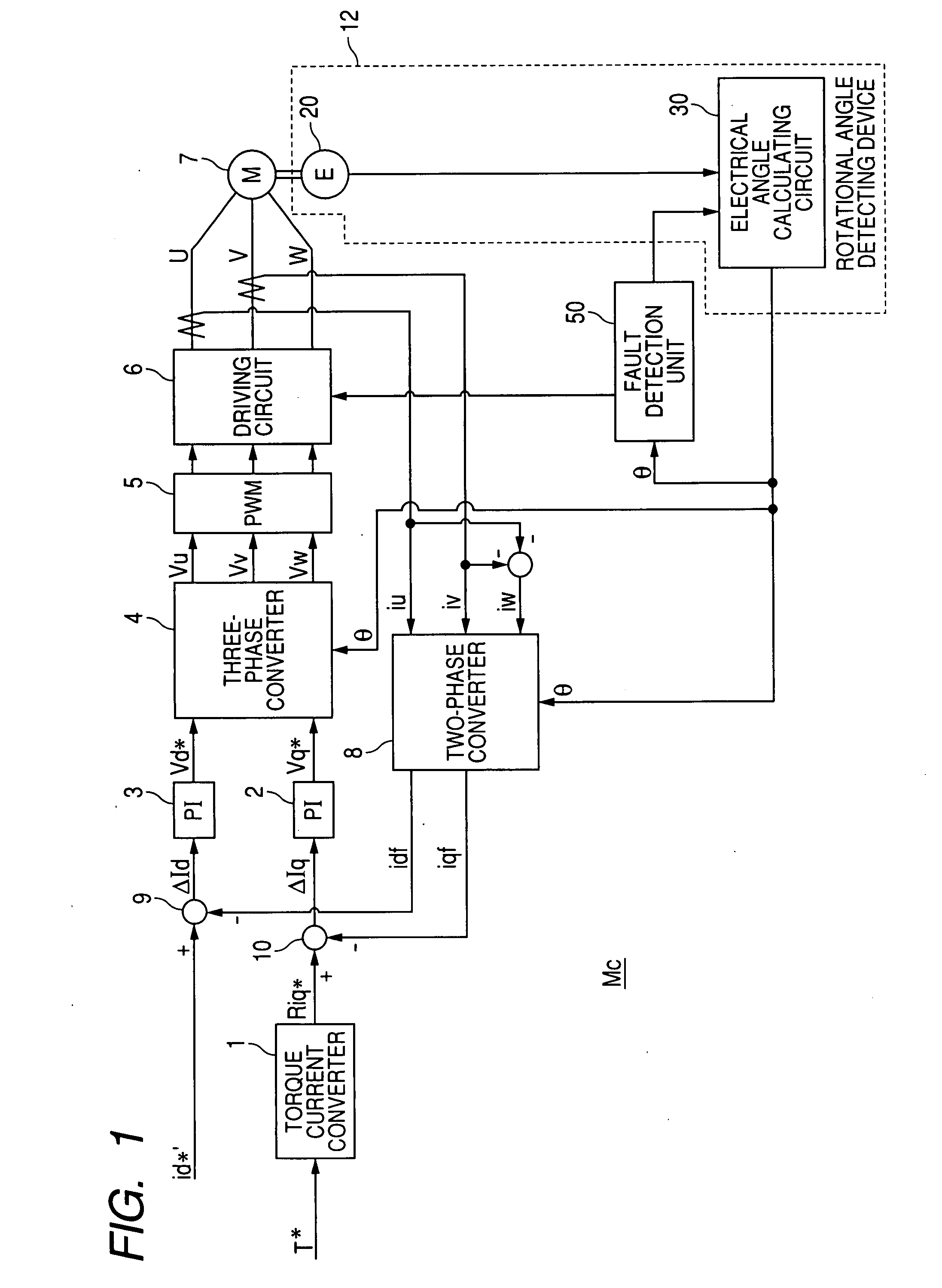
[0026]FIG. 1 is a block diagram of a motor controller according to this embodiment. An electrically operated power steering unit of a vehicle is, for example, driven by a motor operated under control of a motor controller Mc. As described later in detail, the controller Mc has a rotational angle detecting device and a fault detection unit for detecting a fault occurred in the device. The controller Mc receives electric power from a power source such as a battery (not shown) of the vehicle.

[0027]As shown in FIG. 1, the controller Mc adjusts a three-phase alternating current in response to a torque instruction τ* and a magnetizing current id*, and a brushless motor 7 receives the alternating current from the controller Mc. The motor 7 has a cylindrical stator and a columnar rotor disposed so as to be surrounded by the stator. The rotor has a plurality of magnetic poles aligned along a circumferential direction of the stator. The rotor is rotated on its center axis in response to the a...


PUM


Abstract

A fault detection unit detects a fault occurred in a detecting device which detects a rotational angle of a rotor with respect to a stator from sine and cosine wave signals having amplitudes modulated in a sinusoidal wave shape in a cycle of rotation of the rotor. The unit produces a judging value from the signals, judges occurrence of a fault from the value placed out of a normal range, and judges the device to be in a tentative fault state when the judgment is continued. After this judgment, when the rotational angle is changed over its entire range while the value is placed within the normal range, the unit judges the device to have returned to a normal state. In contrast, when the judgment is still continued, the unit judges the device to be in a determinate fault state and decides the occurrence of the fault.

Description

CROSS-REFERENCE TO RELATED APPLICATION[0001]This application is based upon and claims the benefit of priority of the prior Japanese Patent Application 2006-225795 filed on Aug. 22, 2006 so that the contents of which are incorporated herein by reference.BACKGROUND OF THE INVENTION[0002]1. Field of the Invention[0003]The present invention generally relates to a fault detection unit which is used for a rotation angle detecting device for detecting a rotation angle of a rotor with respect to a stator and detects the occurrence of a fault in the device.[0004]2. Description of Related Art[0005]As well known, a rotational angle detecting device is used to detect a rotation angle of a rotor with respect to a stator by using a resolver. In this device, an exciting signal having a predetermined periodic waveform is supplied to a resolver, a sine-wave phase signal and a cosine-wave phase signal are output from the resolver in response to the exciting signal, and each of the phase signals is am...

Claims


Application Information

Patent Timeline
IPC IPC(8): G06F11/30
CPCG01D5/24466G01D5/24461
Inventor KAMEYA, HISASHIHIDAKA, KENICHIRO
Owner DENSO CORP
Why Eureka
Try Eureka