Projectile that marks the strike point

a projectile and strike point technology, applied in the field of projectiles, can solve the problems of contaminating other projectiles, loading jams, and lost tim

Active Publication Date: 2008-03-06
RHEINMETALL WAFFE MUNITION GMBH
View PDF12 Cites 57 Cited by
  • Summary
  • Abstract
  • Description
  • Claims
  • Application Information

AI Technical Summary

Benefits of technology

[0006]It is the object of the invention to prevent the og

Problems solved by technology

When handling such projectiles, the ogive of a projectile in the belt occasionally breaks open when it strikes an object, at least partially releasing the marking material and contaminating other projectiles.
It is even worse if, for example, the projectile is improperly aligned in the

Method used


Image

  • Projectile that marks the strike point
  • Projectile that marks the strike point
  • Projectile that marks the strike point

Examples


Embodiment Construction

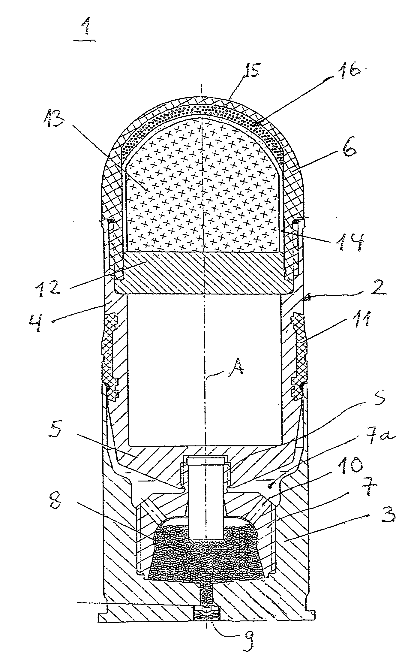
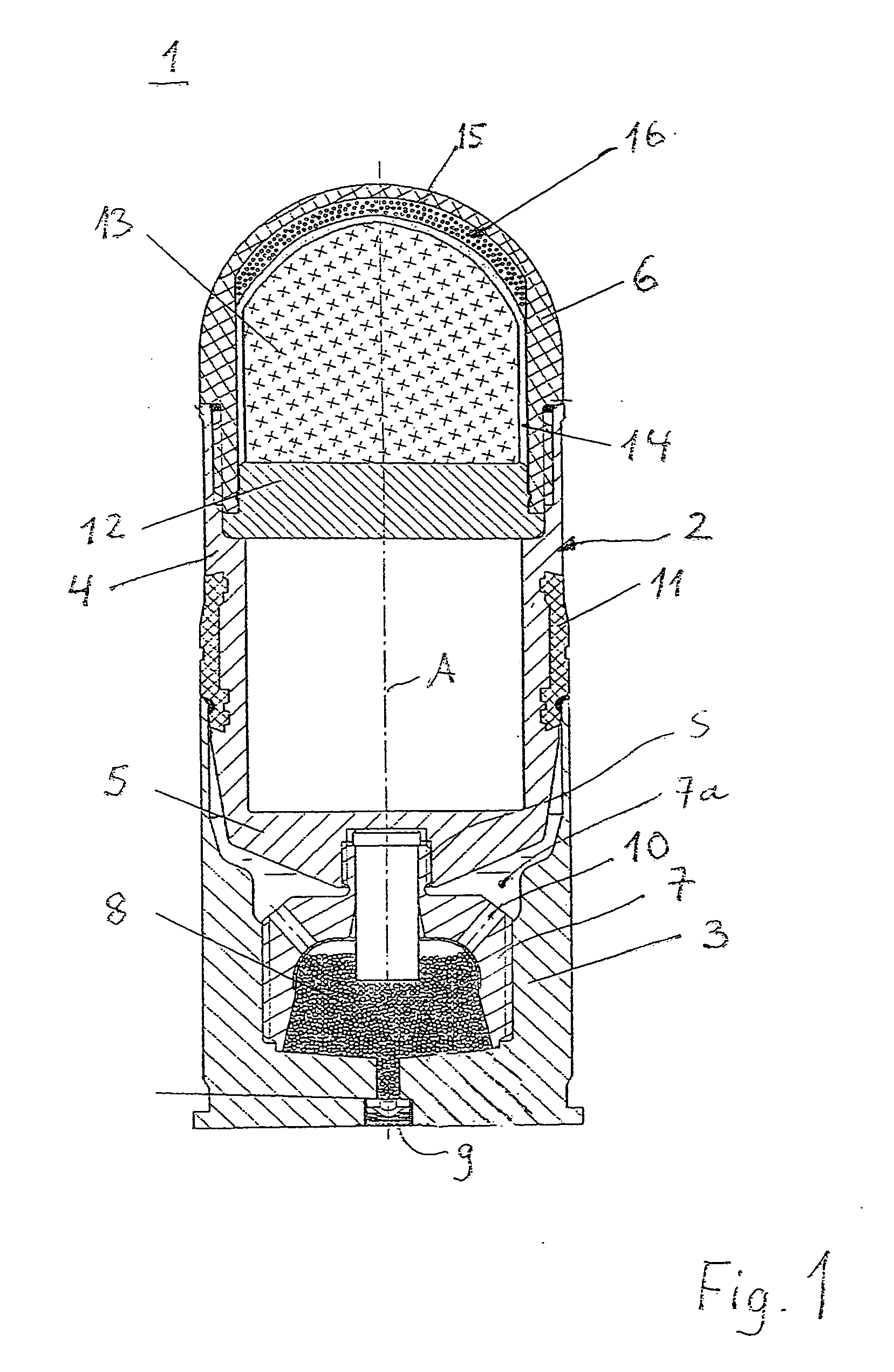
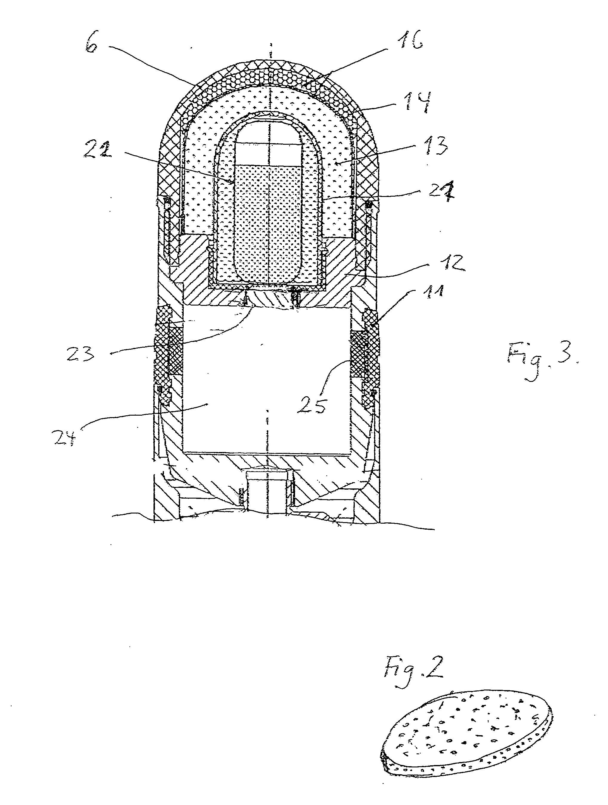
[0008]In accordance with the invention, a projectile of the above- mentioned type is provided, within whose ogive a marking material is inserted, whereby the marking material is protected by a protective cap that bursts when the projectile strikes the target.

[0009]The marking material is also adequately protected by the protective cap if the ogive is broken by improper handling so that no marking material is released.

[0010]Protection may be increased if an intermediary space is left between the inner walls of the ogive of the protective cap near the projectile tip.

[0011]Such an intermediary space is preferably provided with filler material, which may be, for example, a soft foam resting on the inner wall of the ogive and the outer wall of the protective cap. The filler material essentially serves to catch any splinters when the ogive bursts that otherwise may have harmed the protective cap.

[0012]If, for example, the ogive is damaged within the firing chamber of a rapid-fire cannon b...


PUM


Abstract

A projectile, particularly a practice round, has a projectile body that includes a hollow ogive that bursts upon striking the target into which marking material is inserted. The marking material is released when the projectile strikes the target and the ogive bursts. The marking material is covered by a protective cap that breaks when the projectile bursts on the target.

Description

BACKGROUND OF THE INVENTION[0001]The invention relates to a projectile, particularly to a practice round, with a projectile body including a hollow ogive (cup-shaped head) that bursts upon striking the target. This ogive contains dye, particularly a colored powder, whereby the marking material is released to mark the strike point when the projectile strikes the target and when the ogive bursts.[0002]In a practice round, e.g., a practice projectile or a practice bomb that itself does not include live explosive, it is important to mark the strike point on the target so that optimal practice results may be obtained.[0003]For this, the projectile includes at its tip an ogive into which the marking material, e.g., a reddish dye powder, is inserted. The ogive is made of a material such as plastic that bursts when it strikes the target, releasing the dye powder. The dye is scattered for a certain radius around the strike point, and is also scattered by the wind, thus showing the strike poi...

Claims


Application Information

Patent Timeline
IPC IPC(8): F42B12/40F42B8/14
CPCF42B12/40F42B8/14
Inventor HAESELICH, DETLEF
Owner RHEINMETALL WAFFE MUNITION GMBH
Why Eureka
Try Eureka