
Actuation system for an oilfield tubular handling system

a tubular handling and oilfield technology, applied in the direction of drilling pipes, drilling casings, borehole/well accessories, etc., can solve the problems of increasing the complexity of the tubular handling system, and the difficulty of controlling the well

Active Publication Date: 2008-03-06
NABORS DRILLING TECH USA INC
View PDF22 Cites 23 Cited by
  • Summary
  • Abstract
  • Description
  • Claims
  • Application Information

AI Technical Summary

Benefits of technology

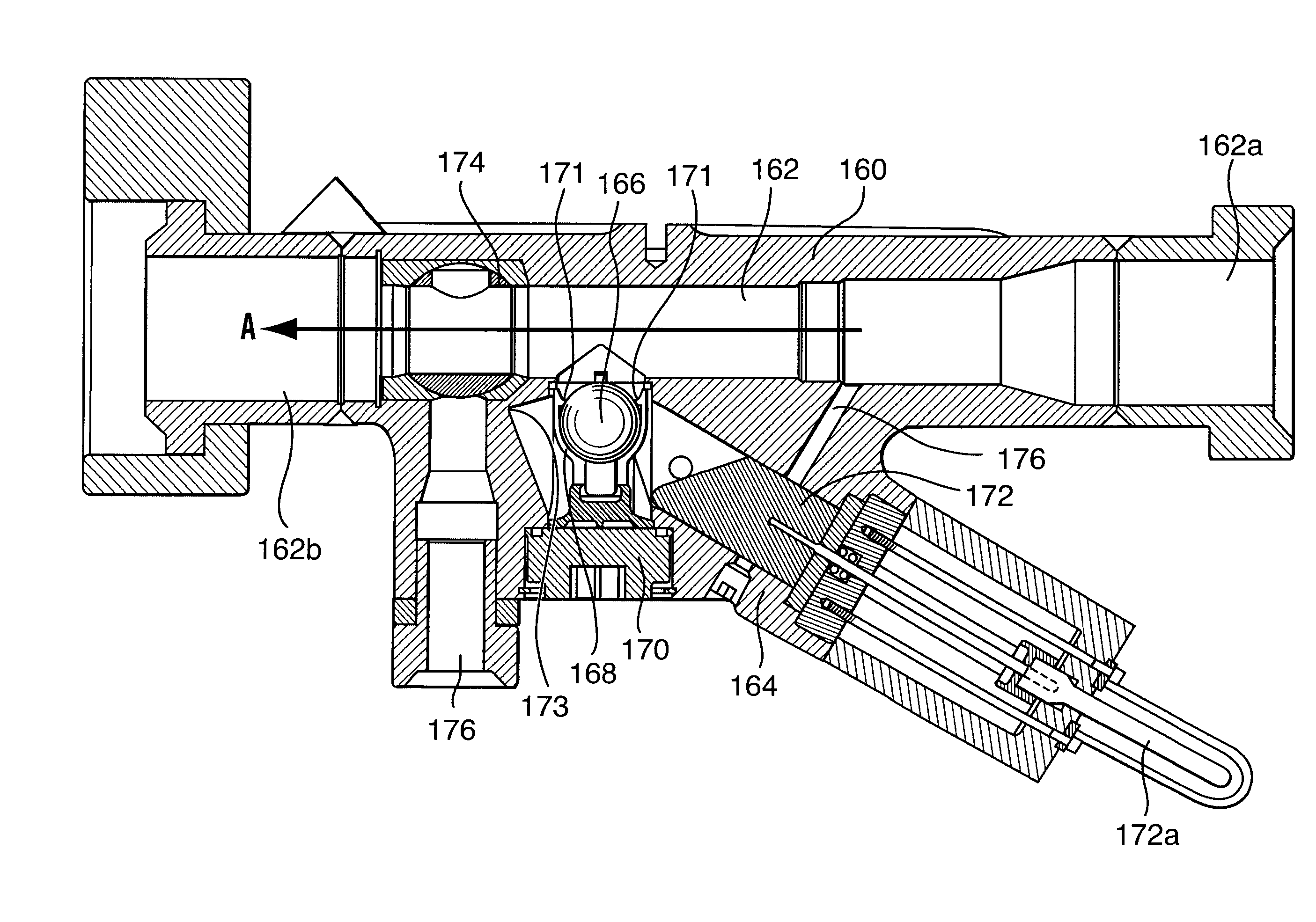
The present invention provides a ball launching assembly and a method for inserting a ball in an oilfield tubular handling system. The assembly includes a body with a bore and a ball holding area connected to the bore, a valve in the bore, and a ball releasably contained in the ball holding area. The method involves retaining the ball in the holding area, connecting the holding area with the mudline, and flowing fluid through the system to move the ball into the flowbore of the housing. The technical effects of the invention include improved handling of balls in oilfield tubular handling systems, simplified operation, and improved reliability.

Problems solved by technology

In a situation where both the draw works and the spear seal fail, the well may be very difficult to control.
Because the spear is often a rotating part, actuation mechanisms for spear-carried tubular handling mechanisms can add to the complexity of tubular handling systems.

Method used


Image

  • Actuation system for an oilfield tubular handling system
  • Actuation system for an oilfield tubular handling system
  • Actuation system for an oilfield tubular handling system

Examples


Embodiment Construction

[0020] The detailed description set forth below in connection with the appended drawings is intended as a description of various embodiments of the present invention and is not intended to represent the only embodiments contemplated by the inventor. The detailed description includes specific details for the purpose of providing a comprehensive understanding of the present invention. However, it will be apparent to those skilled in the art that the present invention may be practiced without these specific details.

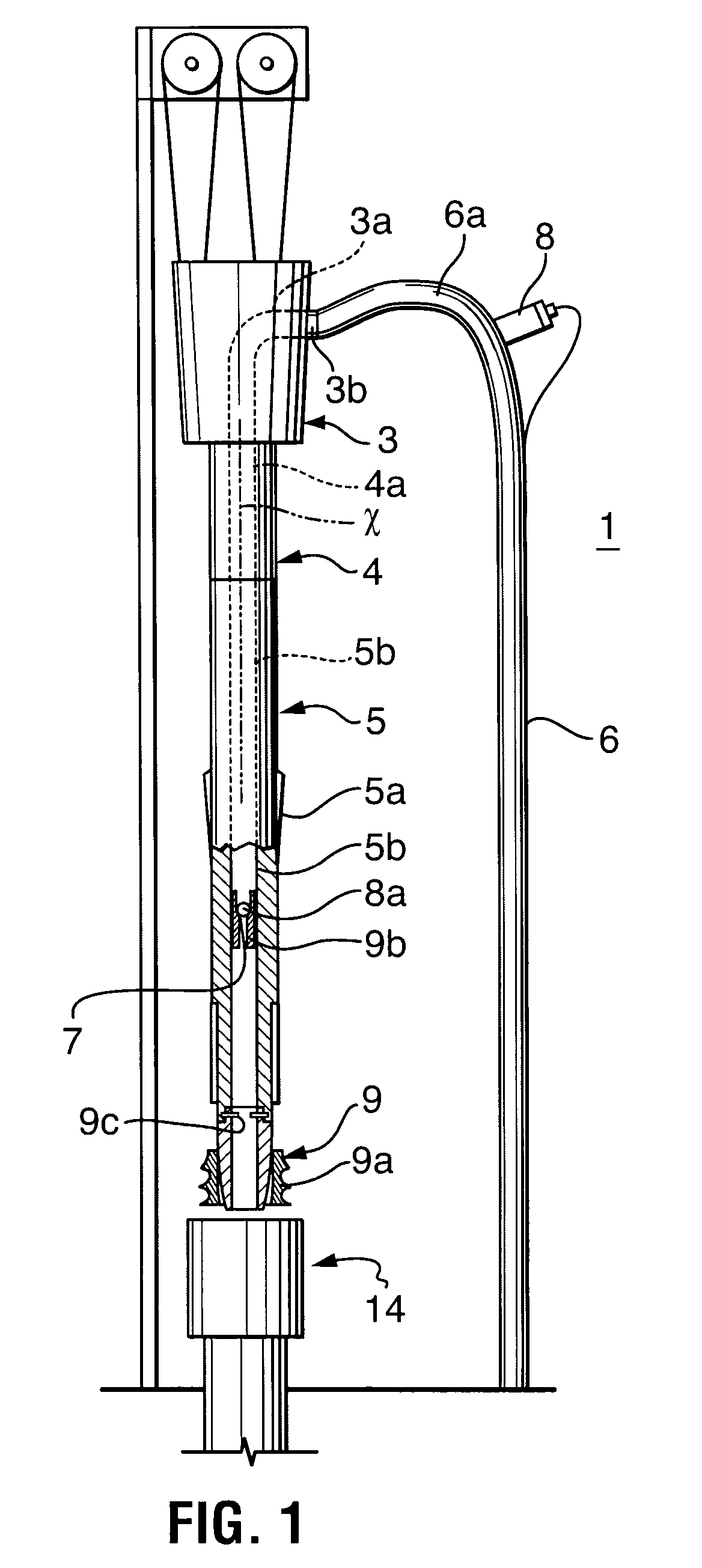
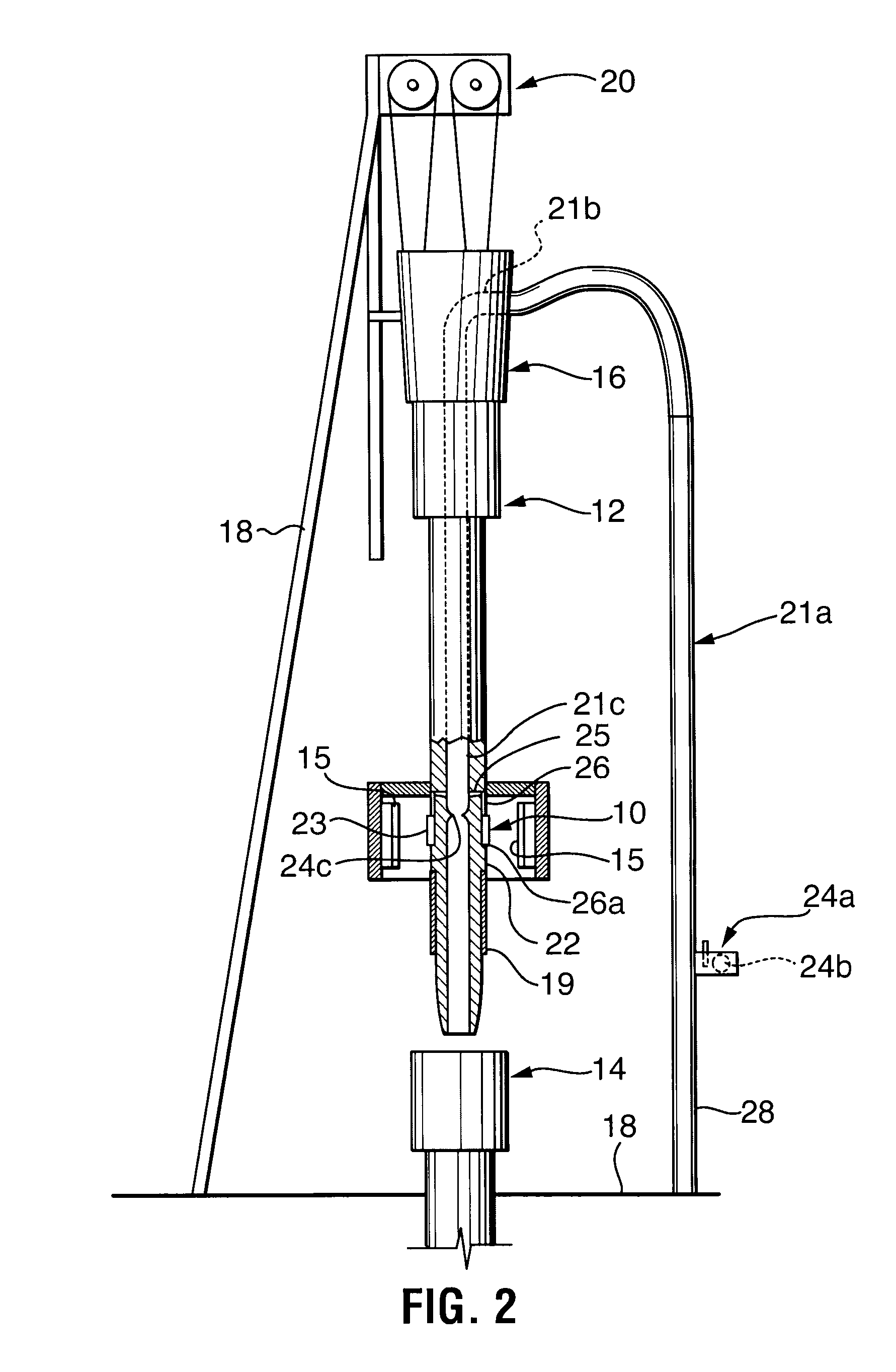
[0021] Referring to FIG. 1, an oilfield tubular handling system 1 is shown for manipulating tubulars and which includes an actuator system. The oilfield tubular handling system includes a vertically movable power drive assembly 3, a longitudinally extending output shaft 4, a pipe gripping mechanism 5, a mud line 6 and an actuation system including a valve seat 7 and a ball drop assembly 8.

[0022] The power drive assembly 3 is operable to provide rotary drive to various part...


PUM


Abstract

An actuation system for a tubular handling mechanism of a tubular handling assembly, the actuation system comprising: a mud flow path passing through rotating parts and non-rotating parts of the tubular handling assembly; a valve assembly including a valve seat in the mud flow path and a ball, the valve seat positioned to be in hydraulic driving communication with the tubular handling mechanism; and a ball drop assembly including an opening to the mud flow path through which the ball is released and wherein the ball drop assembly opening is positioned in a non-rotating part.

Description

FIELD OF THE INVENTION [0001] The present invention relates to an oilfield tool assembly and, in particular, to an actuation system for use during oilfield tubular string handling. BACKGROUND OF THE INVENTION [0002] During oilfield drilling and borehole completion operations tubular strings may be handled in the form of a drill string, a casing string or a liner string for drilling and / or lining the borehole, etc. To grip a tubular and the tubular string, a tubular gripping tool may be used. In some operations, such as casing drilling and / or casing running, tubular gripping tool in the form of a casing clamp may be used to grip the string at its upper end. [0003] A tubular gripping tool may be connected for manipulation by a top drive or other device, the entire assembly being suspended in a rig or derrick by a draw works, if desired. [0004] Tubular gripping tools may include gripping means that engage the tubular being handled. Gripping means may include, for example, devices that ...

Claims


Application Information

Patent Timeline
Patent Type & Authority Applications(United States)
IPC IPC(8): E21B34/00
CPCE21B19/06E21B33/16E21B33/068
Inventor ANGMAN, PER G.
Owner NABORS DRILLING TECH USA INC
Learn More