Volume Displacement System for Irrigation Span

a displacement system and irrigation span technology, applied in watering devices, horticulture, agriculture, etc., can solve the problems of increasing the wear of motors, gears, shafts, etc., and achieve the effect of reducing the effective internal volume, reducing the amount of water carried, and reducing the overall weight of the field

Inactive Publication Date: 2008-03-06
LINDSAY CORP
View PDF13 Cites 8 Cited by
  • Summary
  • Abstract
  • Description
  • Claims
  • Application Information

AI Technical Summary

Benefits of technology

[0003]The present invention provides a way of keeping the large diameter of the pipes for their structural benefits but reducing the effective internal volume of such spans so as to reduce the amount of water carried thereby, thus decreasing their overall weight in the field. In one preferred embodiment, an elongated displacement body such as a thin-walled tube of PVC material with closed ends is inserted into the span to occupy a portion of the space otherwise available for liquid flow. The displacement body is smaller in transverse dimension than the inside diameter of the span so as to create a flow path outside of the body between it and the interior surface of the span. Spacers can be utilized at a number of locations along the length of the span to keep the displacement body spaced away from outlets that might otherwise be blocked by the body. For strength purposes, the tubular body may have internal stiffening struts or the like or may be filled with a suitable rigid synthetic resinous foam that fills the interior of the body to resist collapse of the sidewalls thereof. In another embodiment the displacement body may comprise a member constructed of a suitable rigid synthetic resinous foam material without a surrounding thin-walled pipe or the like, provided that the member has a relatively low rate of water absorption and has sufficient structural integrity to withstand the internal pressures within the span and the abrasion from flowing water.

Problems solved by technology

However, when such large spans become filled with water, the increased weight can cause a number of significant problems, including the formation of excessively deep wheel ruts and increased wear on shafts, motors, gears and other components.

Method used


Image

  • Volume Displacement System for Irrigation Span
  • Volume Displacement System for Irrigation Span
  • Volume Displacement System for Irrigation Span

Examples


Embodiment Construction

[0010]The present invention is susceptible of embodiment in many different forms. While the drawings illustrate and the specification describes certain preferred embodiments of the invention, it is to be understood that such disclosure is by way of example only. There is no intent to limit the principles of the present invention to the particular disclosed embodiments.

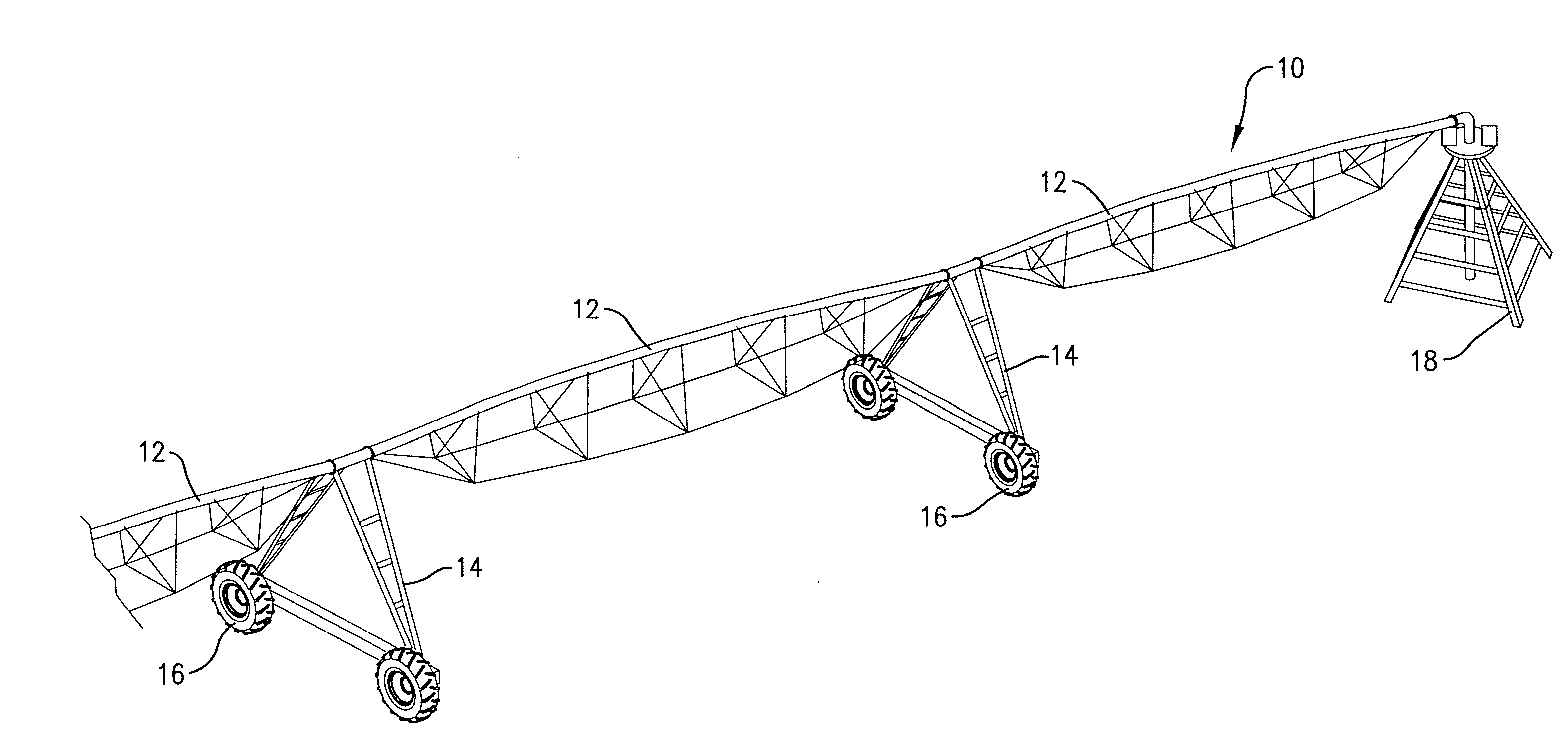
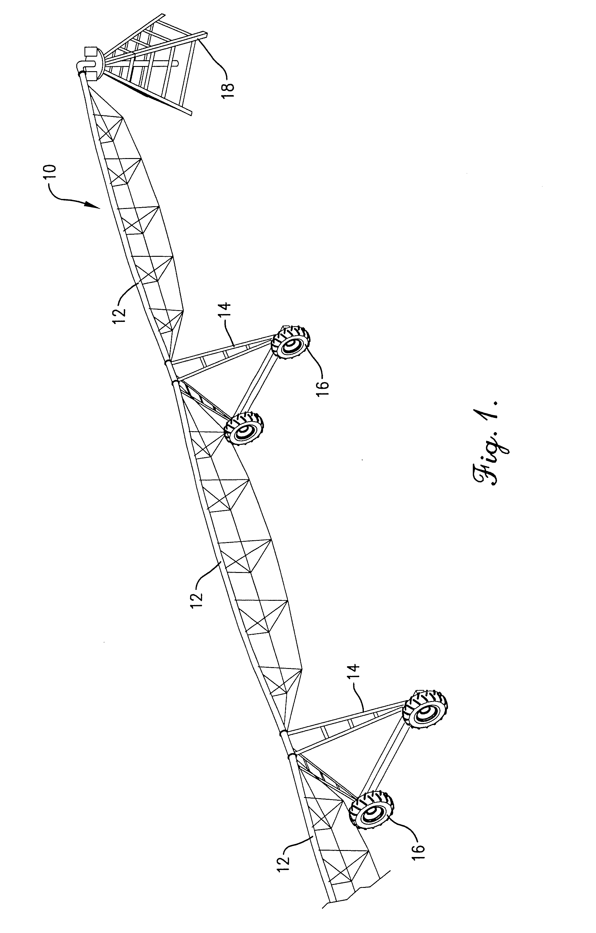
[0011]The irrigation system 10 selected for illustration in FIG. 1 includes a series of serially connected pipe spans 12 that are supported by movable towers 14 having ground wheels 16. Wheels 16 may be driven by suitable means such as electric motors (not shown) so as to transport spans 12 over ground to be irrigated. U.S. Pat. Nos. 4,693,425 and 6,231,450, assigned to the assignee of the present invention, disclose one suitable drive arrangement for the spans of an irrigation system and are hereby incorporated by reference into the present specification. FIG. 1 illustrates the spans 12 as part of a center pivot irrig...


PUM


Abstract

A pipe span of a mobile irrigation system has an elongated volume displacement body contained within the interior flow passage of the span so as to occupy space that would otherwise be available for liquid flow. The displacement body is of reduced transverse dimension relative to the inside diameter of the span so as to present a flow path around the outside of the body between the latter and the sidewall of the span. The length of the body selected for use depends upon the desired amount of volume to be displaced. Alternative embodiments of the displacement body include a tubular member with closed, opposite ends, a thin-walled tubular member provided with a rigid foam insert for strength, a thin-walled tubular member with internal stiffeners, and a rigid foam member devoid of a surrounding thin-walled tubular member.

Description

TECHNICAL FIELD[0001]This invention relates to the field of mobile irrigation equipment and, more particularly, to a unique construction for the liquid-carrying pipe spans of such systems.BACKGROUND AND SUMMARY[0002]Mobile irrigation systems sometimes stretch for great distances in the field. As a consequence, in order to structurally strengthen the long pipe spans of such systems it is a common practice to make the spans larger in diameter than necessary to handle water demands of the field. However, when such large spans become filled with water, the increased weight can cause a number of significant problems, including the formation of excessively deep wheel ruts and increased wear on shafts, motors, gears and other components.[0003]The present invention provides a way of keeping the large diameter of the pipes for their structural benefits but reducing the effective internal volume of such spans so as to reduce the amount of water carried thereby, thus decreasing their overall w...

Claims


Application Information

Patent Timeline
Patent Type & Authority Applications(United States)
IPC IPC(8): B05B3/00
CPCA01G25/092
Inventor KORUS, THOMAS J.
Owner LINDSAY CORP
Why Eureka
Try Eureka