Hospital waste treatment

a technology for treating waste and hospitals, applied in the direction of medical waste disposal, solid separation, grain milling, etc., can solve the problems of hospital waste, difficult to distinguish harmless waste from infectious waste, and all hospital waste must be treated

Inactive Publication Date: 2008-03-06
TRINOVA MEDICAL WASTE SOLUTIONS
View PDF12 Cites 19 Cited by
  • Summary
  • Abstract
  • Description
  • Claims
  • Application Information

AI Technical Summary

Benefits of technology

[0009] The present invention addresses the above and other needs by providing a waste treatment system which shreds waste material into small pieces and soaks the pieces in a liquid disinfectant. The system includes a feed hopper, a shredder, a wetting area, an air operated pump, a dwell area, vibratory de-watering apparatus, and a de-watering auger. Unprocessed waste material is dumped into the feed hopper. The feed hopper feeds the unprocessed waste material into the shredder. The shredder incl...

Problems solved by technology

In the normal course of operation, hospitals generate a variety of waste which is not suitable for normal disposal.
While some or most hospital waste may be harmless, it is difficult to distinguish such harmless waste from infectious waste.
As a result, all of the waste from a hospital must be treated as if it may be harmful.
Also, sensitivity to the handling of hospital waste has been raised as a result of AIDS and other health issues.
Recently, the bird flu spread rapidly and initially was not well understood.
Unfortunately, incinerators may be difficult to construct and operate, and may create environmental issues.
Autoclaves may also be expensive and difficult to operate.
Unfortunately, while the systems described in the '925 and the '248 patents successfully treat most hospital waste, some hospital waste has been found to contain material, such as titanium prosthetic joints, which ...

Method used


Image

  • Hospital waste treatment
  • Hospital waste treatment
  • Hospital waste treatment

Examples


first embodiment

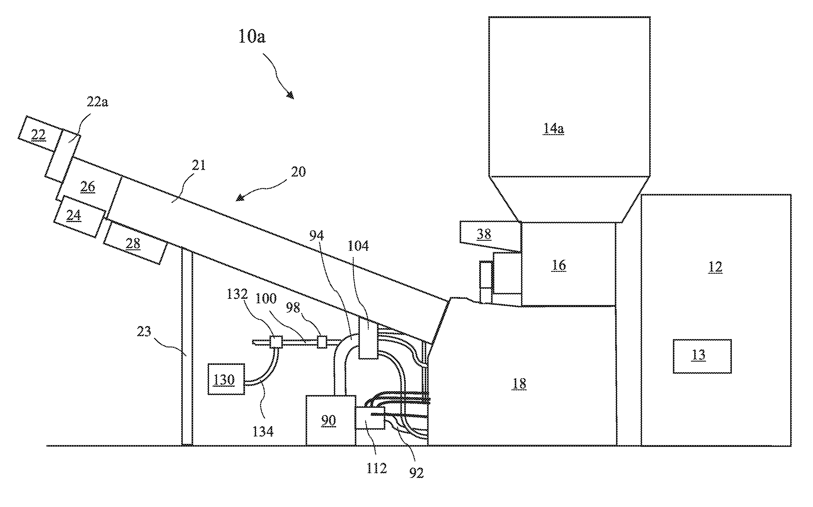
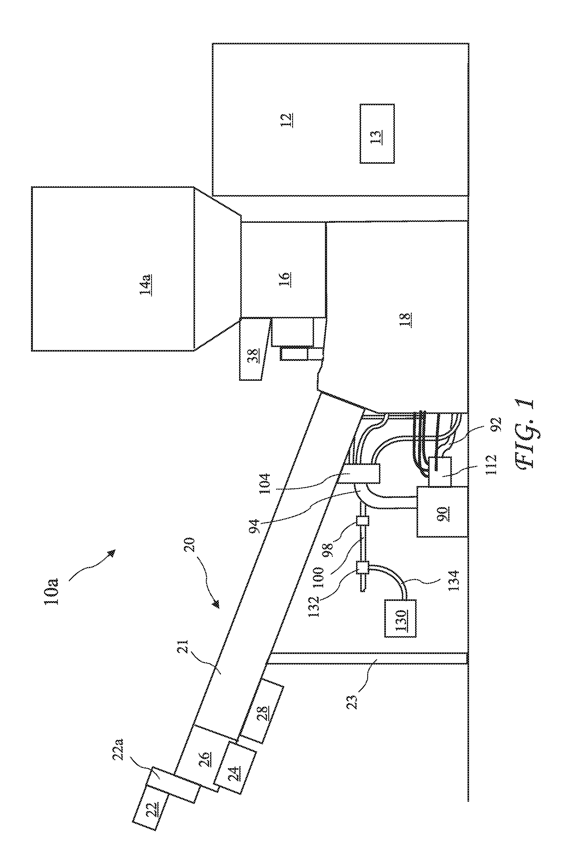
[0050] a waste treatment system 10a according to the present invention is shown in FIG. 1. The waste treatment system 10a includes a cage 12, first feed hopper 14a, a shredder 16, a wetting area comprising a main solution tank 18, and a dwell area comprising an auger 20. A hospital waste container 40 (see FIGS. 2A and 2B) is placed into the cage 12 where a lift unit 42 lifts the container 40 and dumps hospital waste carried in the container 40 into the feed hopper 14a (see FIGS. 2A and 2B). The feed hopper 14a resides above the shredder 16 and feeds the waste into the shredder 16. The shredder 16 shreds the waste, and the shredded waste drops into the main solution tank 18 where the shredded waste is wetted in a disinfectant liquid to create a wetted slurry. The auger 20 is in fluid cooperation with the main solution tank 18 and lifts the wetted slurry from the main solution tank 18 and completes the waste treatment.

[0051] A radioactive material detector 13 resides in the cage 12. W...

third embodiment

[0114] An overview of a waste treatment system 10c according to the present invention is shown in FIG. 22. The waste treatment system 10c includes all of the components and features of the waste treatment system 10b, with the exception of the de-watering system 220 described in FIGS. 16 and 16A. The waste treatment system 10c replaces the de-watering system 220 with a vibtrator de-watering system 300 and a de-watering auger 302. The recovered disinfectant liquid is returned to main tank 232 from both the circular vibtrator de-watering system 300 and the de-watering auger 302 through line 226. De-watered waste material is collected in container 304. An example of a suitable vibratory de-watering apparatus is a circular vibratory de-watering apparatus made by Sweco in Florance, Ky.

[0115] A more detailed view of the de-watering apparatus is shown in FIG. 23 and a cross-sectional view of the vibratory de-watering apparatus 300 taken along line 24-24 of FIG. 23 is shown in FIG. 24. The v...


PUM


Abstract

A waste treatment system shreds waste material into small pieces and soaks the pieces in a liquid disinfectant. The system includes a feed hopper, a shredder, a wetting area, an air operated pump, a dwell area, vibratory de-watering apparatus, and a de-watering auger. Unprocessed waste material is dumped into the feed hopper. The feed hopper feeds the unprocessed waste material into the shredder. The shredder includes a rotor and anvil for shredding the unprocessed waste material. The shredded material falls into the wetting area where the shredded material is wetted with the liquid disinfectant to create a wetted slurry. The wetted slurry is advanced by an air operated pump into a dwell-area for an additional three to four minutes of wetted time in the dwell-area before entering the vibratory de-watering apparatus and then the auger. The total wetting time allows the waste material to be completely disinfected.

Description

[0001] The present application is a Continuation In Part of U.S. application Ser. No. 11 / 568,352, filed Oct. 26, 2006, for “HOSPITAL WASTE TREATMENT” which is Continuation In Part of U.S. application Ser. No. 11 / 212,009, filed Aug. 25, 2005, for “HOSPITAL WASTE TREATMENT WITH IMPROVED DISINFECTANT LIQUID PRODUCTION” which is Continuation In Part of U.S. application Ser. No. 11 / 190,343, filed Jul. 26, 2005 for “INFECTIOUS WASTE TREATMENT” which applications are incorporated in their entirety herein by reference.TECHNICAL FIELD [0002] The present invention relates to a device and method for treatment of waste and in particular to the treatment of infectious waste from a hospital. BACKGROUND ART [0003] In the normal course of operation, hospitals generate a variety of waste which is not suitable for normal disposal. While some or most hospital waste may be harmless, it is difficult to distinguish such harmless waste from infectious waste. As a result, all of the waste from a hospital m...

Claims


Application Information

Patent Timeline
IPC IPC(8): A61L2/18B02C19/00
CPCA61L11/00
Inventor JAKOBI, FELIX F.BENNETT, JAMES F.
Owner TRINOVA MEDICAL WASTE SOLUTIONS
Why Eureka
Try Eureka