Hybrid power harvesting and method

a power harvesting and hybrid technology, applied in the direction of mechanical energy handling, mechanical equipment, machines/engines, etc., can solve the problems of high cost and maintenance requirements of many devices, disruptive to the entire system, and high cost of scheduled power source maintenance, etc., and achieve high efficiency rf

Active Publication Date: 2008-03-06
POWERCAST
View PDF12 Cites 242 Cited by
  • Summary
  • Abstract
  • Description
  • Claims
  • Application Information

AI Technical Summary

Benefits of technology

[0012] A method and apparatus for high efficiency RF rectification for various loads, which is suitable for use with the present invention, has been discussed in detail in U.S. Provisional Patent Application No. 60 / 729,792, which is incorporated herein by reference.
[0013] The invention pertains to one or more receivers collecting energy that is transmitted from one or more sources. After collection of the energy, the receivers transform the energy into a form or power useable by an end device, such as, but not limited to direct current (DC) power using a converting circuit, power harvester, or energy harvester. The end device(s) may be wireless sensors, solid-state lighting, or the recharging of batteries. It is the focus of the invention to describe transmitting multiple types of energy to one or more receivers. One transmitter may transmit more than one type of energy, and one receiver may receive more than one type of energy. There may be more than one transmitter of one type of energy in a given area, making a network of transmitters. Conversely, there may be more that one receiver for receiving energy from one transmitter, or a network of transmitters. Likewise, one or more receivers may receive energy from more than one transmitter, or a network of transmitters.

Problems solved by technology

Even with power conscious designs and the latest in battery technology, many devices do not meet the lifetime cost and maintenance requirements for applications that require a large number of untethered devices, such as logistics and building automation.
For both device types, scheduled power-source maintenance is costly and can be disruptive to the entire system that a device is intended to monitor and / or control.
Unscheduled maintenance trips are even more costly and disruptive.
On a macro level, the relatively high cost associated with the internal battery also reduces the practical, or economically viable, number of devices that can be deployed.
However, this ideal solution may not always be practical to implement due to low energy in the environment and site restrictions that limit the ability to use a dedicated energy supply.

Method used


Image

  • Hybrid power harvesting and method
  • Hybrid power harvesting and method
  • Hybrid power harvesting and method

Examples


Embodiment Construction

[0033] A complete understanding of the invention will be obtained from the following description when taken in connection with the accompanying drawing figures wherein like reference characters identify like parts throughout.

[0034] For purposes of the description hereinafter, the terms “upper”, “lower”, “right”, “left”, “vertical”, “horizontal”, “top”, “bottom”, and derivatives thereof shall relate to the invention as it is oriented in the drawing figures. However, it is to be understood that the invention may assume various alternative variations and step sequences, except where expressly specified to the contrary. It is also to be understood that the specific devices and processes illustrated in the attached drawings, and described in the following specification, are simply exemplary embodiments of the invention. Hence, specific dimensions and other physical characteristics related to the embodiments disclosed herein are not to be considered as limiting.

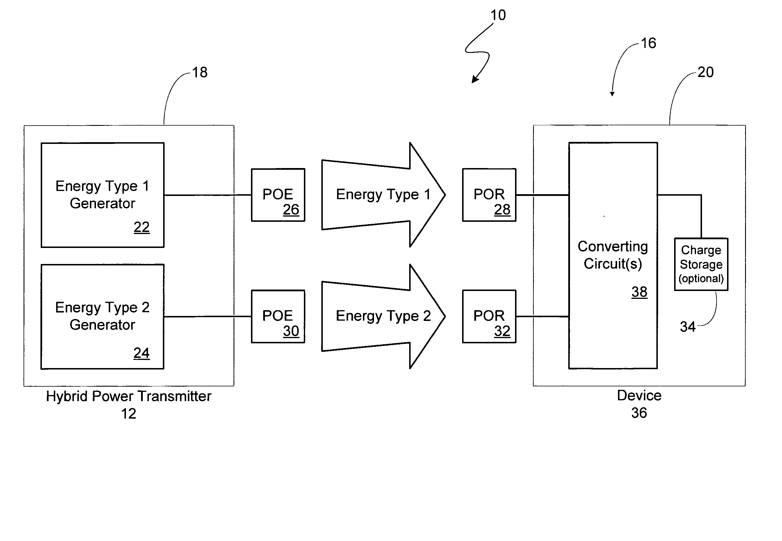
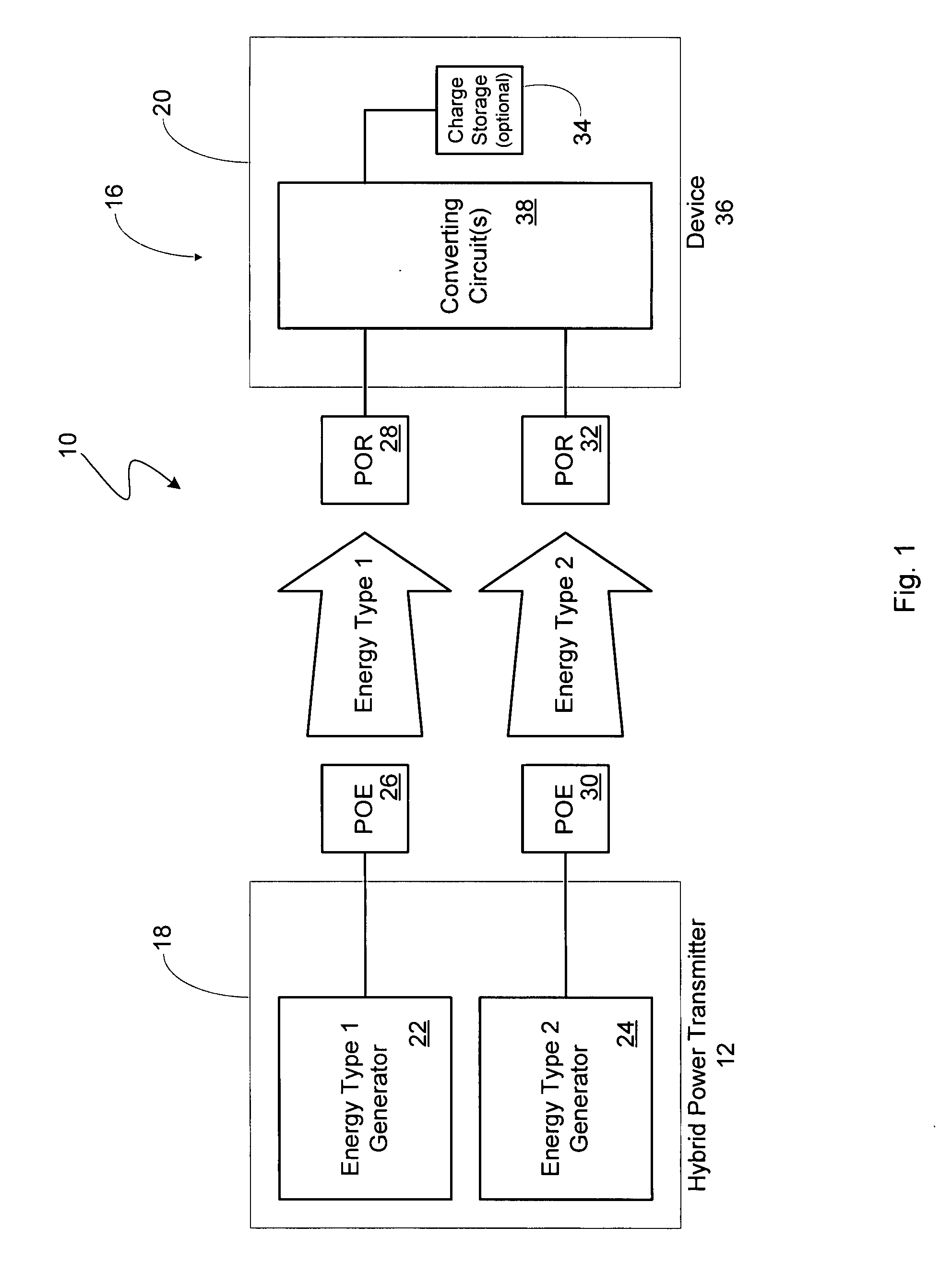
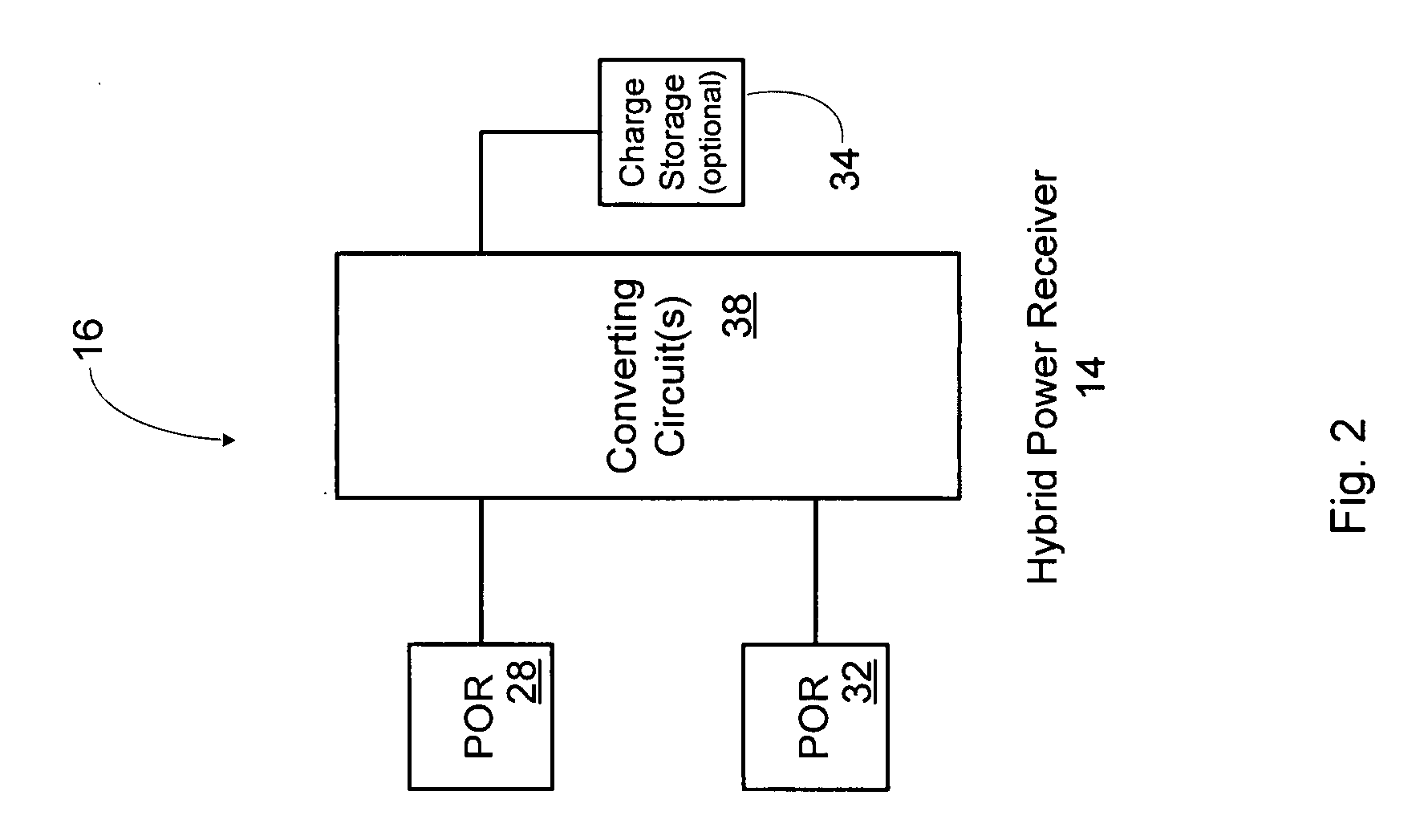
[0035] The present invent...


PUM


Abstract

A system of providing energy includes a transmitter for sending wirelessly a first type of energy and at least a second type of energy different from the first type of energy. The system includes a receiver for receiving wirelessly the first type of energy and converting it to usable energy. A transmitter for transmitting power wirelessly. A receiver for receiving wirelessly transmitted power. A method for providing energy.

Description

FIELD OF THE INVENTION [0001] The present invention is directed to power harvesting transmitters, receivers, and systems that combines two or more types of energy for wireless power transfer. The invention preferably uses radio frequency (RF) energy as a source of energy. BACKGROUND OF THE INVENTION [0002] As processor capabilities have expanded and power requirements have decreased, there has been an ongoing explosion of devices that operate completely independent of wires or power cords. These “untethered” devices range from cell phones and wireless keyboards to building sensors and active Radio Frequency Identification (RFID) tags. [0003] Engineers and designers of these untethered devices continue to have to deal with the limitations of portable power sources, primarily using batteries as the key design parameter. While the performance of processors and portable devices has been doubling every 18-24 months (driven by Moore's law), battery technology in terms of capacity has only...

Claims


Application Information

Patent Timeline
Patent Type & Authority Applications(United States)
IPC IPC(8): H02K7/18
CPCH02J17/00H02J50/10H02J50/20H02J50/40H02J50/001H02J50/05
Inventor GREENE, CHARLES E.HARRIST, DANIEL W.SHEARER, JOHN G.
Owner POWERCAST
Why Eureka
Try Eureka