Ballasts for Fluorescent Lamps

a technology for fluorescent lamps and ballasts, which is applied in the field of circuits for fluorescent lamps, can solve the problems of lamp shattering, overheating or possibly failing of ballasts, etc., and achieve the effect of simple configuration and simple configuration

Active Publication Date: 2008-03-06
FULHAM CO LTD
View PDF18 Cites 17 Cited by
  • Summary
  • Abstract
  • Description
  • Claims
  • Application Information

AI Technical Summary

Benefits of technology

[0006]Methods and apparatus for driving a load such as a fluorescent lamp provide an integrated circuit, a circuit for sensing increased voltage across an output for a load, and a

Problems solved by technology

Sustained higher power delivery may cause the ballast

Method used


Image

  • Ballasts for Fluorescent Lamps
  • Ballasts for Fluorescent Lamps
  • Ballasts for Fluorescent Lamps

Examples


Embodiment Construction

[0023]This specification taken in conjunction with the drawings sets forth examples of apparatus and methods incorporating one or more aspects of the present inventions in such a manner that any person skilled in the art can make and use the inventions. The examples provide the best modes contemplated for carrying out the inventions, although it should be understood that various modifications can be accomplished within the parameters of the present inventions.

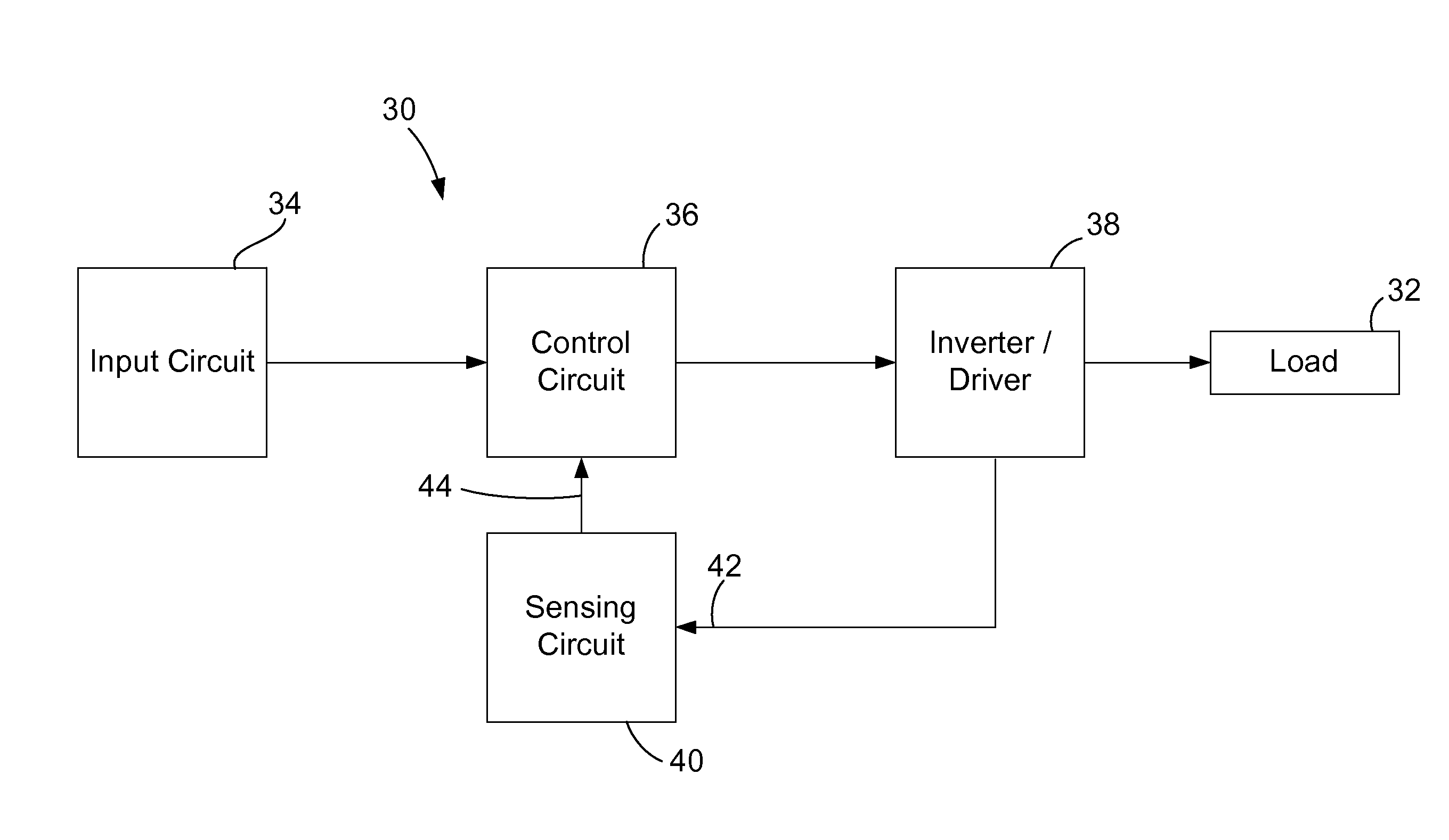
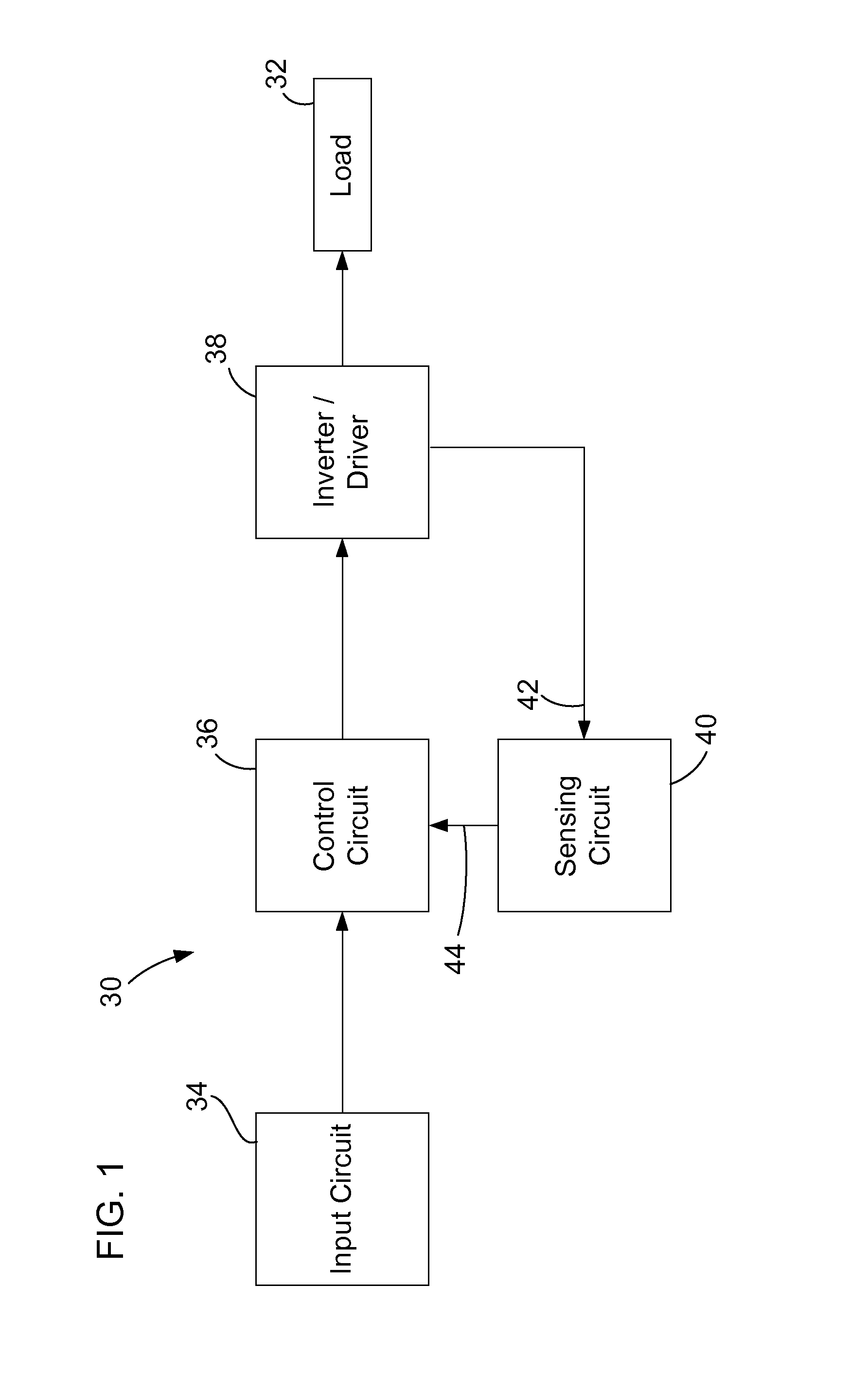
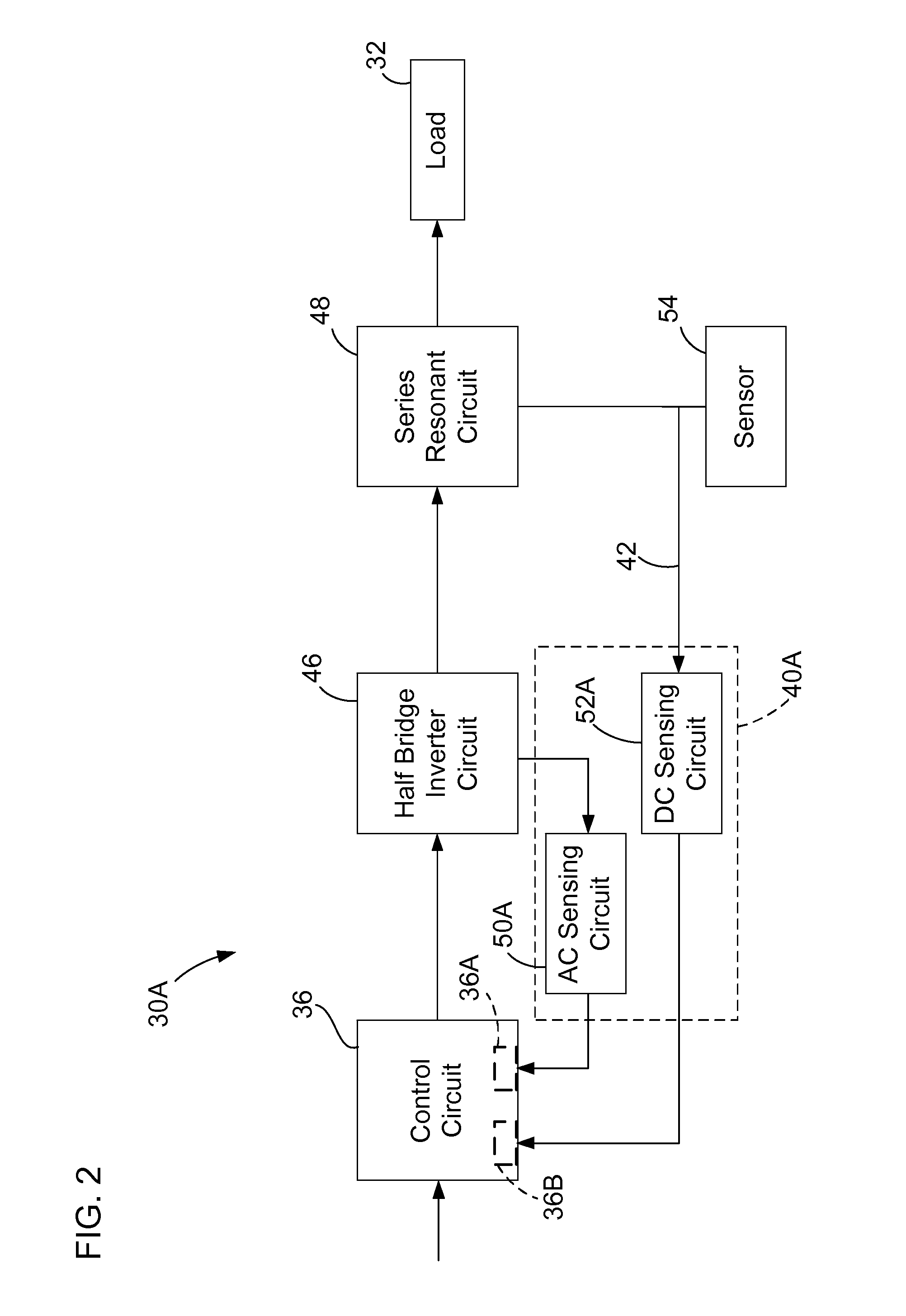
[0024]Examples of circuits and of methods of using the circuits are described. Depending on what feature or features are incorporated in a given structure or a given method, benefits can be achieved in the structure or the method. For example, sensing circuits in series with a series resonant circuit may allow sensing possible end-of-lamp life conditions, and a separate re-strike monitoring circuit may provide more flexibility in operation without needing more expensive components.

[0025]These and other benefits will become more...


PUM


Abstract

Circuits are disclosed, for example for driving fluorescent lamps, and such circuits may form part of a ballast. First and second sensing circuits can apply respective signals to a control circuit as a function of an end-of-lamp life condition and of the number of re-strike attempts.

Description

BACKGROUND[0001]1. Field[0002]This relates to circuits for fluorescent lamps, including ballast circuits having sensing and / or control circuits that operate in part in a manner relating to incipient failure of the lamp and which produce a limited number of multiple re-strikes of a lamp.[0003]2. Related Art[0004]Power supply circuits such as ballasts for fluorescent lamps may include integrated circuits. These ballasts are electronic ballasts, and they are widely used to power lighting circuits, including conventional fluorescent lamps, compact fluorescent lamps, and other fluorescent lighting components. Electronic ballasts are capable of performing a number of functions, which may include pre-heating of the lamp filaments, driving inverter circuits for providing AC power to the lamp, and various shutdown functions. Some proprietary integrated circuits may also include end-of-lamp life shutdown circuits, automatic ballast reset upon lamp replacement and control of the number of re-s...

Claims


Application Information

Patent Timeline
IPC IPC(8): H05B39/04
CPCH05B41/2985H05B41/2828
Inventor SHACKLE, PETER WWU, ZHIQING
Owner FULHAM CO LTD
Why Eureka
Try Eureka