Wheel condition detector and wheel condition monitor

Active Publication Date: 2008-03-06
TOYOTA JIDOSHA KK
View PDF7 Cites 16 Cited by
  • Summary
  • Abstract
  • Description
  • Claims
  • Application Information

AI Technical Summary

Benefits of technology

[0012]The present invention provides a wheel condition detector and a wheel condition monitor, which prevent foreign matter as much as possible from entering a wheel condition detection space through a communication section, thereby maintaining normal detection performance.

Problems solved by technology

In addition, the term “foreign matter” herein may mean any material as long as the material can enter the detection space through the communication section and impair desired detection performance of the condition sensor.
However, the restriction means restricts the entry of the foreign matter into the detection space through the communication section.

Method used


Image

  • Wheel condition detector and wheel condition monitor
  • Wheel condition detector and wheel condition monitor
  • Wheel condition detector and wheel condition monitor

Examples


first embodiment

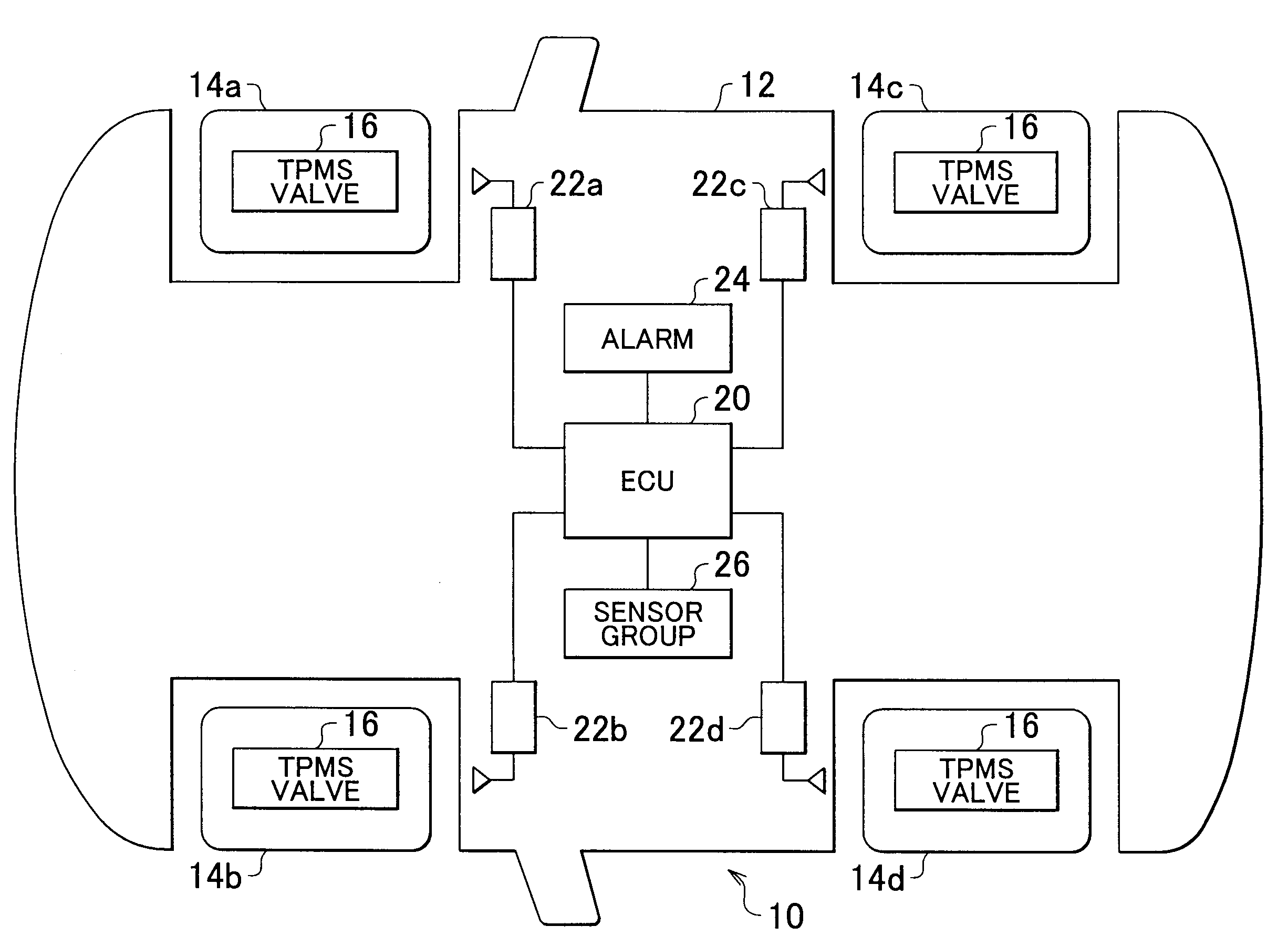
[0048]FIG. 1 is a schematic diagram of a vehicle having a wheel condition monitor according to the invention. FIG. 2 is a partial sectional view of a wheel mounted on the vehicle of FIG. 1. As shown in FIG. 1, a vehicle 10 has four wheels rotatably supported on a vehicle body 12. They include a right front wheel 14a, a left front wheel 14b, a right rear wheel 14c, and a left rear wheel 14d (hereinafter sometimes collectively called as “wheel 14”). Various units are mounted on the vehicle body 12, such as engine, transmission, steering system, brake system (they are not shown), and electronic control unit (hereinafter referred to as “ECU”). The engine is a driving source for driving wheels. The transmission is designed to transmit a driving force at a given gear ratio. The steering system is designed to steer the wheels. The brake system is designed to apply a braking force to the wheels. The ECU is designed to control these units.

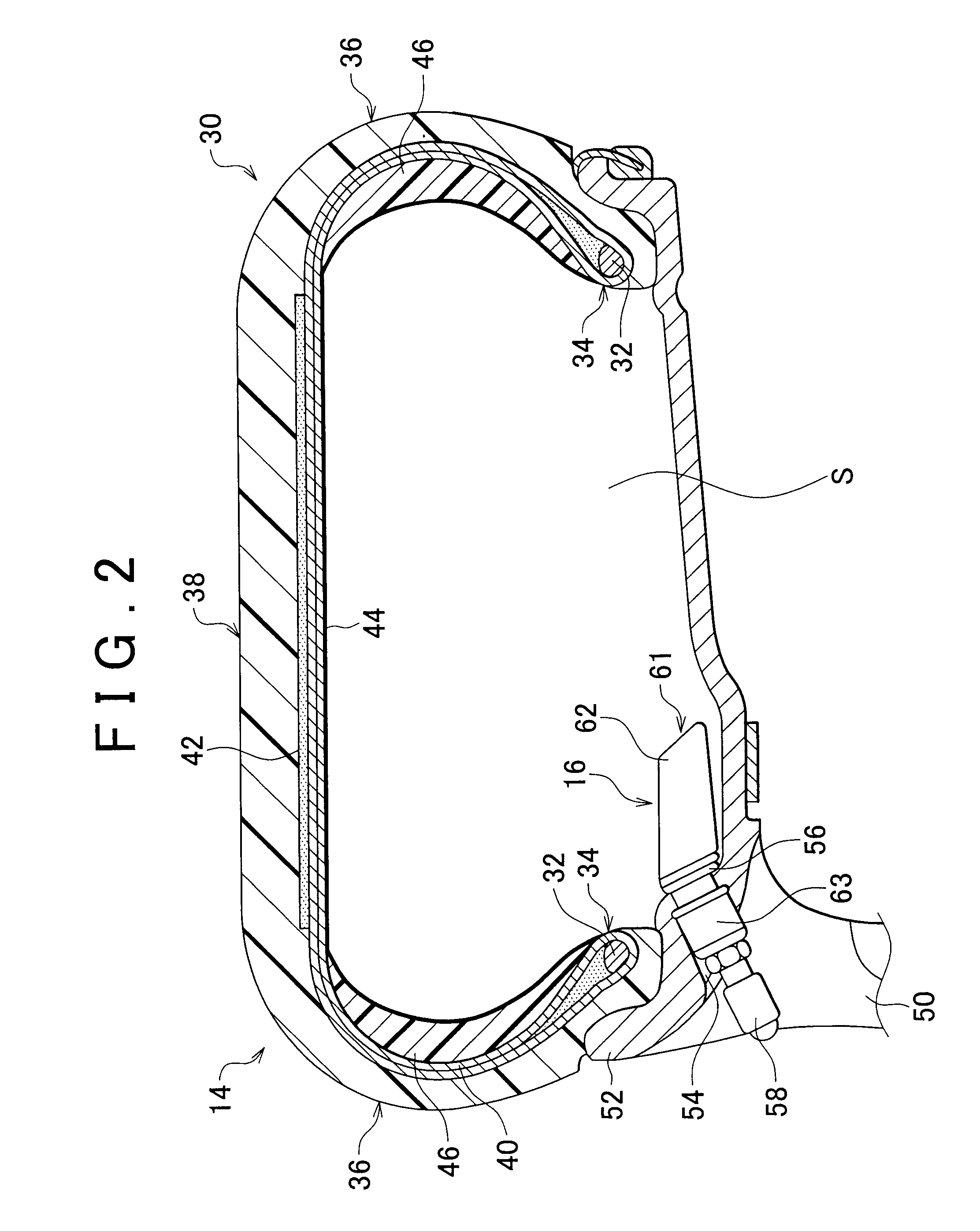
[0049]The wheel 14, including a tire and a wheel memb...

second embodiment

[0073]FIG. 7 is a schematic side sectional view of a TPMS valve according to the invention. In a TPMS valve 216, an opening-closing mechanism 280 includes an opening-closing member 281 and a spring 282. The opening-closing member 281 has a communication passage 271 therein. The spring 282 is an elastic member that impels the opening-closing member 281 in the closing direction.

[0074]The opening-closing member 281 has a base section 283 and a communication hole forming section 284. The base section 283 moves along inner walls of the detection space S2 towards or away from the air pressure sensor 67. The communication hole forming section 284 has a cylindrical shape that extends from the center of the base section 283 in a direction opposite from the air pressure sensor 67. A guide hole 285 is formed in the case 62. A distal end of the communication hole forming section 284 is inserted slidably through the guide hole 285. A communication passage 271 runs through the communication hole ...

third embodiment

[0082]In another case the acceleration sensor 68 detects zero acceleration, that is, the wheel 14 stops rotating. After a predetermined period of time has elapsed since the detection of the rotation stop, the control circuit 76 drives the actuator 385 to actuate the lid 81 to the open position. More specifically, when the vehicle 10 starts moving after the injection of tire repair agent and then stops, the tire repair agent is displaced over time to the bottom surface of the tire 30 due to the gravity. Thus, the displaced tire repair agent, does not enter the case 62 through the communication hole 71. This brings the communication hole 71 into communication mode, and therefore enables detection of the conditions of the wheel 14 during the stop of the vehicle 10. In the invention, the acceleration sensor 68 may be considered as a stop state detecting section.

[0083]As discussed above, in the third embodiment of the invention, the opening-closing mechanism 380 is also provided for open...


PUM


Abstract

A wheel condition detector and a wheel condition monitor, each having a case provided in an internal space defined between a tire and a wheel member, the tire and the wheel member forming a wheel. The case has a detection space formed therein and a communication section for communicating an interior and an exterior of the detection space with each other. The wheel condition detector or the wheel condition monitor has: a condition sensor located in the detection space that detects a condition of the wheel; and a restriction section that restricts an entry of foreign matter present in the internal space into the detection space through the communication section.

Description

INCORPORATION BY REFERENCE[0001]The disclosure of Japanese Patent Application No. 2006-241155 filed on Sep. 6, 2006 including the specification, drawings and abstract is incorporated herein by reference in its entirety.BACKGROUND OF THE INVENTION[0002]1. Field of the Invention[0003]The present invention relates to a wheel-mounted wheel condition detector that detects the condition of each wheel. The present invention also relates to a wheel condition monitor that monitors the condition of each wheel, the monitor having a wheel-mounted device that transmits information for each wheel and a vehicle-mounted device that receives the information from each wheel.[0004]2. Description of the Related Art[0005]A conventional tire pressure monitoring system (hereinafter referred to as “TPMS”) generally includes a wheel-mounted device and a vehicle-mounted device. The wheel-mounted device is designed to sense tire air pressure (hereinafter sometimes referred to as “tire pressure”) of each wheel...

Claims


Application Information

Patent Timeline
IPC IPC(8): B60C23/02
CPCB60C23/0494B60C23/0408
Inventor MURAKAMI, HIDEKI
Owner TOYOTA JIDOSHA KK
Why Eureka
Try Eureka