Portable position determining device

Inactive Publication Date: 2008-03-06
PFIZER INC
View PDF4 Cites 160 Cited by
  • Summary
  • Abstract
  • Description
  • Claims
  • Application Information

AI Technical Summary

Benefits of technology

[0015] In another aspect of the present disclosure, the object locator system may plot the location information on a map or permit the us

Problems solved by technology

A number of systems have been proposed which employ existing wireless communication capabilities but which tend to be cumbersome, bulky, expensive or all of the above.
However, the global positioning system (GPS) has some disadvantages in that it is relatively slow in acquiring the location data and it is strongly dependent upon the target object being in an open area

Method used


Image

  • Portable position determining device
  • Portable position determining device
  • Portable position determining device

Examples


Embodiment Construction

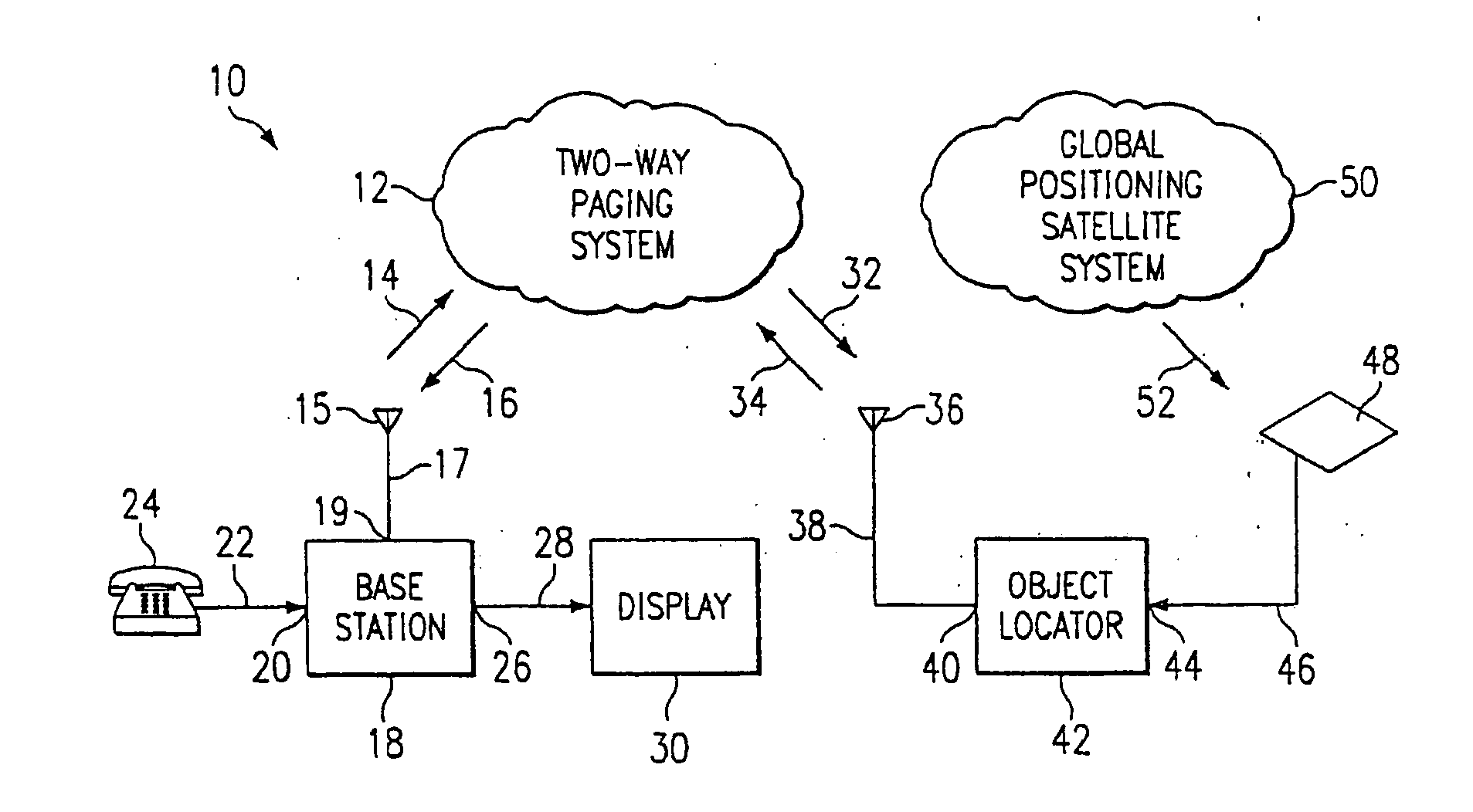
[0046] Referring now to FIG. 1, there is illustrated a system block diagram of the object locator of the present disclosure. In FIG. 1, the object locator system 10 includes a two-way paging system 12, a global positioning satellite system 50 and the object locator 42. The two-way paging system 12 is a conventional paging system that is well known in the art, for example, such as illustrated and described in U.S. Pat. No. 5,423,056 issued Jun. 6, 1995 to Lindquist, et al. and entitled ADAPTIVE CELLULAR PAGING SYSTEM, which patent is incorporated by reference herein in its entirety. The two-way paging system 12 interacts with a base station 18 over a transmit path 14 and a receive path 16. The base station 18 may include a telephone, pager, and the like or may have an input 20 for receiving a dialed-in telephone number from telephone set 24 along communications path 22 or from wireless telephone set 25 over communications path 31. Base station 18 may, in other embodiments, be a pagin...


PUM


Abstract

A position determining device is disclosed comprising a satellite navigation receiver for automatically providing computed position information, when the device has changed its position relative to a predetermined location, to a paging transmitter for transmission to a paging receiver for readout of the computed position information. The readout may be in the form of coordinates and may be accompanied by a message or alarm. The device may be configured as a portable unit of small size and economical manufacture.

Description

CROSS REFERENCE TO RELATED APPLICATIONS [0001] The present application is a Continuation-In-Part of U.S. patent application Ser. No. 11 / 063,254, filed Feb. 22, 2005 and entitled MOBILE OBJECT LOCATOR, which is a continuation of U.S. application Ser. No. 10 / 361,802 filed Feb. 10, 2003 and entitled “MOBILE OBJECT LOCATOR,” which is a continuation of U.S. application Ser. No. 09 / 862,569 filed May 22, 2001 and entitled “MOBILE OBJECT LOCATOR,” which is a continuation of U.S. application Ser. No. 09 / 362,789 filed Jul. 28, 1999 and entitled “MOBILE OBJECT LOCATOR,” which claims the benefit of the filing date of U.S. Provisional Application No. 60 / 140,040, which was filed on Jun. 18, 1999. The contents of U.S. application Ser. No. 11 / 063,254, U.S. application Ser. No. 10 / 361,802, U.S. application Ser. No. 09 / 862,569, U.S. application Ser. No. 09 / 362,789, and U.S. Provisional Application No. 60 / 140,040 are incorporated by reference as part of this application.TECHNICAL FIELD OF THE INVENTIO...

Claims


Application Information

Patent Timeline
IPC IPC(8): H04B7/185G01S19/17G01S19/34
CPCG01S5/0027G08B21/023H04W4/023G08B21/0269G08B21/0261
Inventor MARTUCCI, JENNIFERFOWLER, EUGENE F.MCALEXANDER, JOSEPH C.
Owner PFIZER INC
Why Eureka
Try Eureka