Connecting structure for a lens and a main board
- Summary
- Abstract
- Description
- Claims
- Application Information
AI Technical Summary
Benefits of technology
Problems solved by technology
Method used
Image

Examples
second embodiment
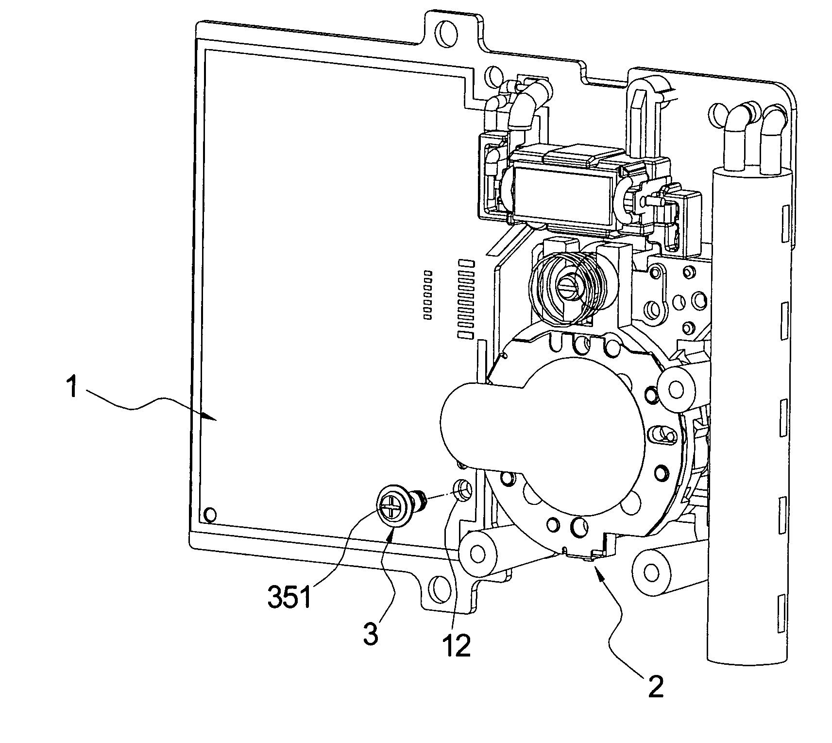
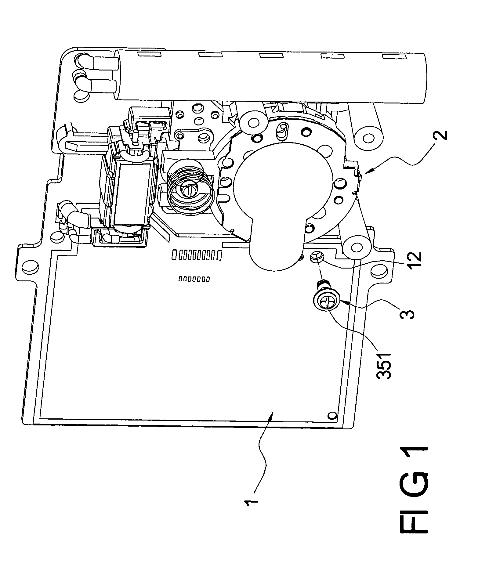
[0028]FIG. 6 shows the present invention. The proper space between the board 1 and the lens module 2 have a cushioning unit 4 that is made of Styrofoam. The cushioning unit 4 is sleeved on the separating part 34 of the connecting device 3.
[0029]Because there is a cushioning unit 4 between the lens module 2 and the board 1, the lens module 2 is positioned well and the MTF of the lens module 2 is kept on its best state.
third embodiment
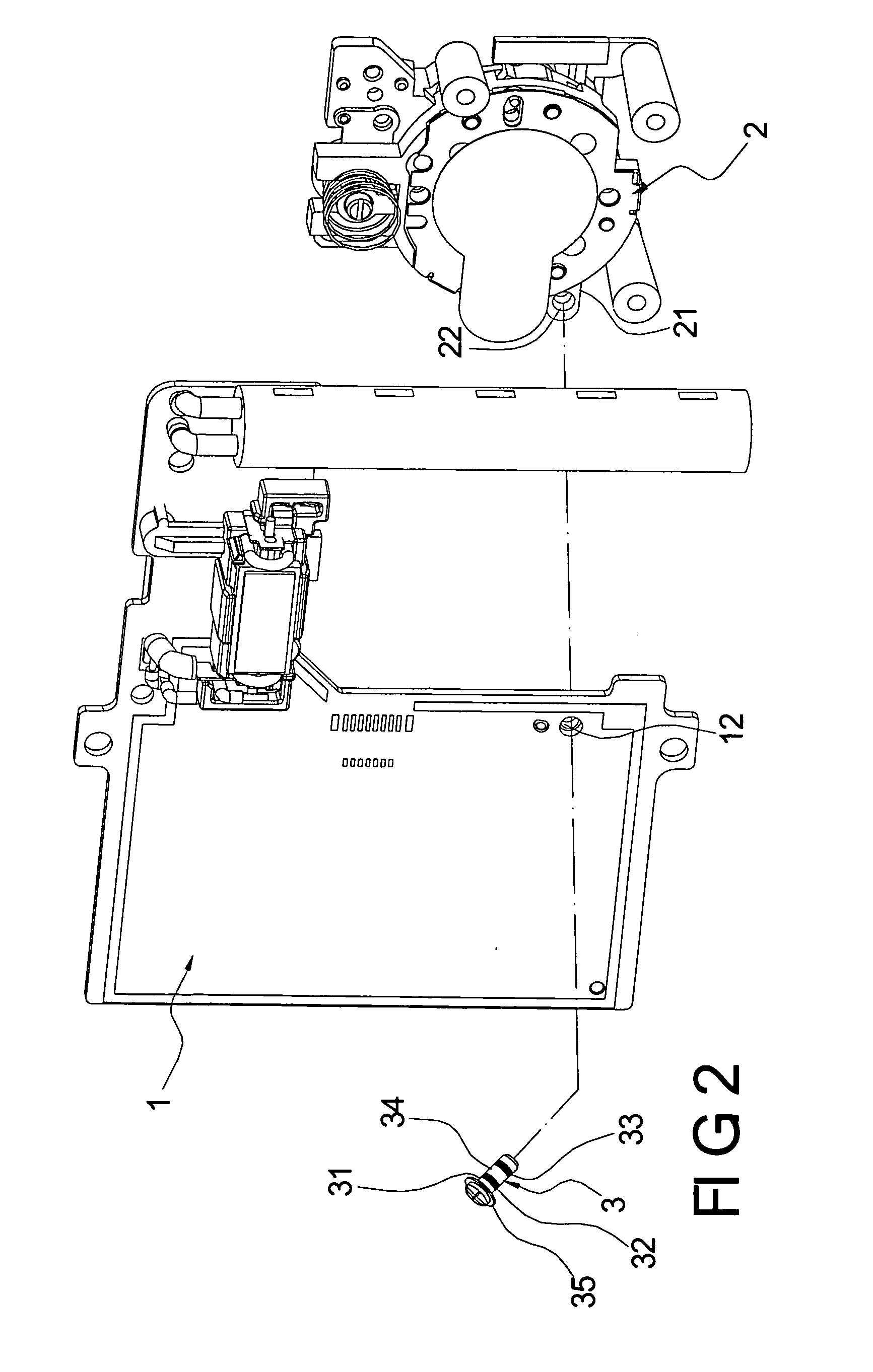
[0030]FIGS. 7 and 8 show the present invention. The first adjusting part 32 of the connecting device 3 is adjacent to the nut 35.
[0031]The first adjusting part 32 and the second adjusting part 33 of the connecting device 3 respectively correspond to the first through hole 12 of the board 1 and the second through hole 22 of the lens module 2. When the lens module 2 is combined and positioned with the board 1, the bottom of the nut 35 leans exactly on the board 1 and there is a cushioning unit 4 between the lens module 2 and the board 1. The lens module 2 is positioned well.
[0032]The present invention has the following characteristics:
[0033]1. The present invention utilizes the connecting device 3 to adjust and control the board 1 and the lens module 2 so that there is a proper space between them both. Therefore, the warp of the board 1 generated in the heating process is located at the separating part 34. The warp of the board 1 will not disturb the lens module 2 so that the lens mod...
PUM
 Abstract
Description
Claims
Application Information