
Adhesive Applicator, and Bookbinding Apparatus and Image-Forming System Equipped with the Applicator

a technology of applicator and adhesive, which is applied in the field of adhesive applicator and bookbinding apparatus and image-forming system equipped with the applicator, can solve the problems of clinging of evaporation derivatives, and clogging of the resupply path, so as to shorten the melt time and ensure supply

Active Publication Date: 2008-03-06
NISCA KK
View PDF3 Cites 16 Cited by
  • Summary
  • Abstract
  • Description
  • Claims
  • Application Information

AI Technical Summary

Benefits of technology

The present invention is an adhesive applicator system that prevents clogging of the adhesive container and allows for quicker supply of adhesive in solid form. The system includes a glue container, adhesive application means, heating means, temperature control means, resupply-hopper means, vacuum-ducting means, and control means. The control means controls the heating and vacuum-ducting means, and the resupply-hopper means and vacuum-ducting means are positioned adjacent to the glue container to prevent evaporation derivatives of adhesive from entering the refill hopper. The glue container is designed to move along the adhesive application surface of the sheet bundle, and the control means activates the heating means at the resupply position to melt the adhesive after it is refilled from the resupply-hopper means. The system also includes a resupply path and an opening / shutting shutter plate to guide solid adhesive to the glue container. The high temperature evaporation derivatives do not adhere or coagulate around when melting solid adhesive, making it possible to smoothly supply a predetermined amount of solid adhesive to the glue container. The glue container is compact and reciprocates along a side edge of the sheet bundle so the adhesive remaining in the container can be heated to a predetermined temperature in a short amount of time, making it possible to smoothly refill adhesive to the glue container.

Problems solved by technology

On the other hand, included in the adhesives generally used are tackifiers and like additives—the main component of which is synthetic rubber—for increasing the adhesives' viscosity, wherein a known problem with these adhesives is that on account of their being heated to and melted at a predetermined temperature (ordinarily 130° C. to 150° C.)
To address this, as disclosed in above-cited Japanese Unexamined Pat. App. Pub. No. 2004-216769, the evaporation derivatives that issue from the glue container when the adhesive inside the container is heated and melted are vacuum-filtered, yet a problem arising therein is that in replenishing the container with adhesive, the evaporation derivatives cling to adhesive furnished in the hopper or other storage, or cling to the resupply path.
The evaporation derivatives that issue from the container melt adhesive furnished within the hopper (adhesive prior to replenishment), or cling to the adhesive and form clots in it, leading to resupply-path clogging problems.
Likewise, evaporation derivatives clinging to the resupply path also leads to the problem of the refilling adhesive getting stuck in and clogging the path.
To counter these problems, in the conventional structure in Pat. App. Pub. No. 2004-216769, a heating device is disposed to one (e.g., the leftmost) side of the reciprocating glue container, and the resupply hopper is disposed to the other (rightmost) side, opposing the heating device, but resupplying the container with solid adhesive in a situation in which adhesive therein has been melted at a high temperature leads to the problems just noted.

Method used


Image

  • Adhesive Applicator, and Bookbinding Apparatus and Image-Forming System Equipped with the Applicator
  • Adhesive Applicator, and Bookbinding Apparatus and Image-Forming System Equipped with the Applicator
  • Adhesive Applicator, and Bookbinding Apparatus and Image-Forming System Equipped with the Applicator

Examples


Embodiment Construction

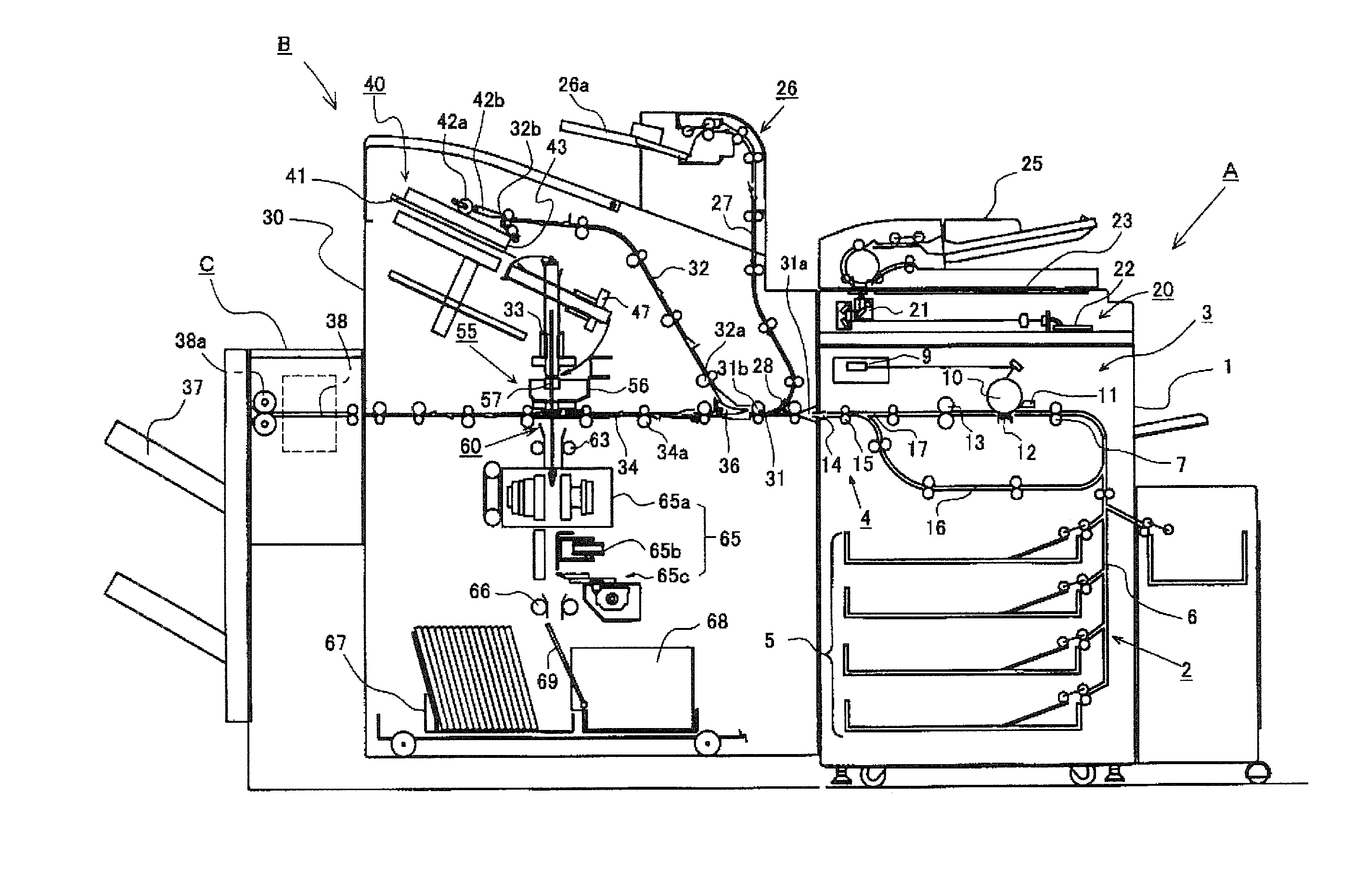
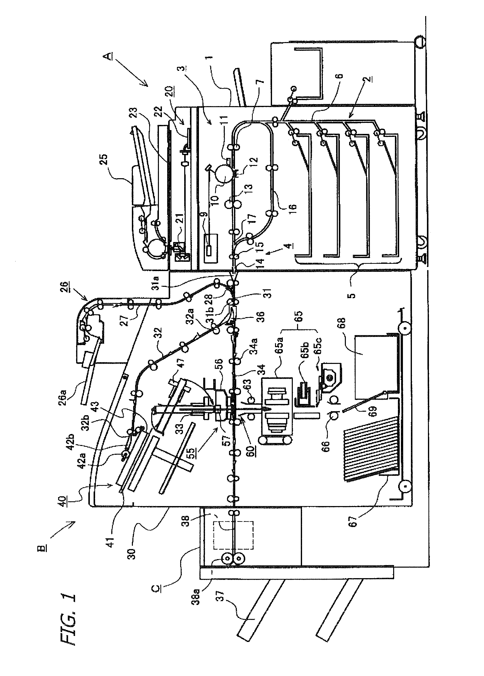
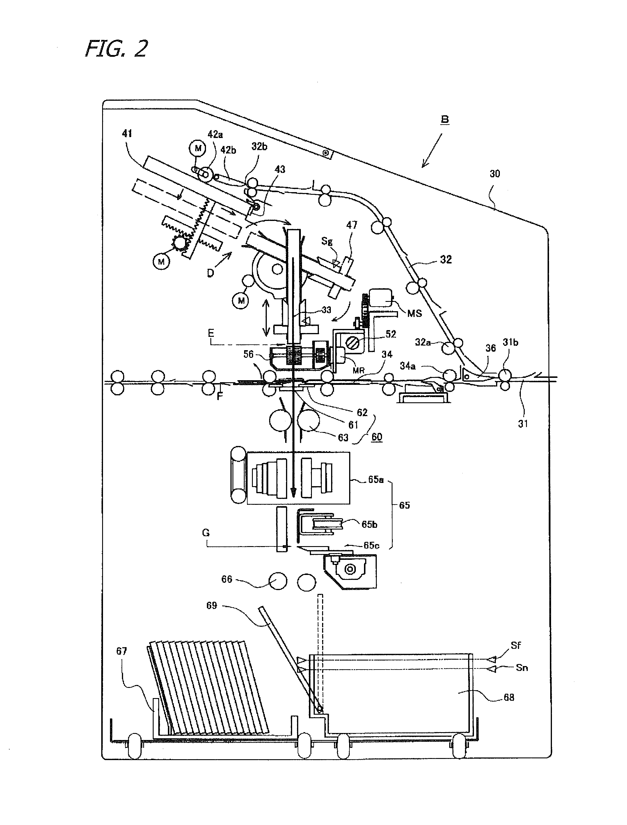
[0028] A preferred embodiment of the present invention will now be explained based on the drawings provided. FIG. 1 is an explanatory view of the bookbinding apparatus according to the present invention and the overall configuration of the image-forming system that uses the bookbinding apparatus; FIG. 2 is a detailed explanatory view of the bookbinding apparatus.

[0029] The image-forming system shown in FIG. 1 is composed of an image-forming apparatus A that sequentially prints sheets; a bookbinding apparatus B installed at a downstream side adjacent to the image-forming apparatus A; and a finisher C disposed downstream of the bookbinding apparatus B. Sheets formed with images by the image-forming apparatus A are bound into a booklet at the bookbinding apparatus B. The configuration allows sheets not requiring the bookbinding process to pass through the bookbinding apparatus B to undergo a finishing process at the finisher C.

[0030] The image-forming apparatus A can implement a vari...


PUM


Abstract

In replenishing a glue container with hot-melt glue, to enable stable supply of the glue in solid form without it clogging the resupply path from the hopper, provided are: a sheet retaining unit for retaining a sheaf in a glue application position; a glue applier in a hot-melt-glue-receiving container, disposed in the glue application position, for applying glue to an endface of a sheaf there; a heater, disposed in the glue container, for heating / melting the glue inside; a heater temperature controller; a resupply hopper above the glue container for replenishing it with solid glue; a vacuum ducting unit above the container and adjoining the resupply hopper, for suctioning up glue evaporation derivatives; and a control unit configured to run the vacuum ducting unit when the glue container is being replenished with glue, to prevent or mitigate invasion of evaporation derivatives into the resupply hopper.

Description

BACKGROUND OF THE INVENTION [0001] 1. Technical Field [0002] The present invention—involving adhesive applicators that apply adhesive to a lateral-edge surface of sheet bundles having been collated into sheaves, and then bind the sheaves together with cover sheets or similar coverings—relates to improvements in refilling mechanisms that supply hot-melt adhesive to a glue container, in bookbinding apparatuses or like machines that collate into sheaves sheets on which images have been formed for example in a printing or other image-forming apparatus, and apply hot-melt adhesive to a sheaf and bind it together with a cover sheet. [0003] 2. Description of the Related Art [0004] Widely known among adhesive applicators of this type are in general those that with an applicator roll or similar device apply to an endface of a sheet sheaf adhesive in liquid form, charged into a container; the adhesives employed in such implementations are hot-melts—adhesives solid at ordinary temperatures, th...

Claims


Application Information

Patent Timeline
Patent Type & Authority Applications(United States)
IPC IPC(8): B42C19/00B42C11/02B42C9/00B42C13/00
CPCB05C11/1042B42C9/0018G03G2215/00936G03G2215/00822B42C11/02
Inventor SORITA, HIROYUKITAKAGI, KATSUMASAOHNO, NORIHIROKONDOU, JUNKUBOTA, KAZUYUKI
Owner NISCA KK
Learn More