Lighting device with a magnetic switch

Inactive Publication Date: 2008-03-13
DOSUN SOLAR TECH
View PDF16 Cites 39 Cited by
  • Summary
  • Abstract
  • Description
  • Claims
  • Application Information

AI Technical Summary

Benefits of technology

[0007]An object of the present invention is to provide a lighting device with a magnetic switch, which can be easily operated by using the com

Problems solved by technology

With respect to multifunctional portable lighting devices such as a flashlight, it is difficult to design the lighting devices where all setting and operations can be controlled by one key because of size, appearance, and waterproofing problems.
For example, in case of using single key to control all functions (such as off-mode 0-

Method used


Image

  • Lighting device with a magnetic switch
  • Lighting device with a magnetic switch
  • Lighting device with a magnetic switch

Examples


Embodiment Construction

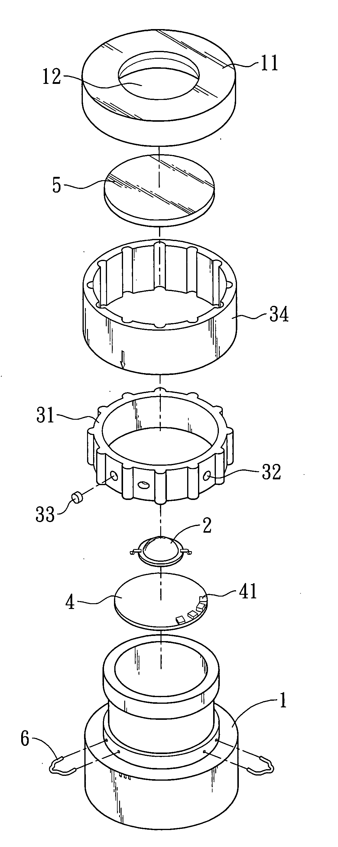
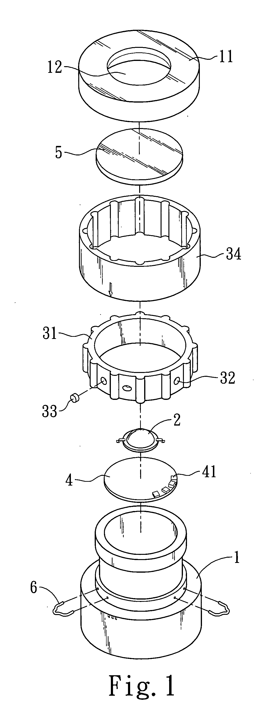
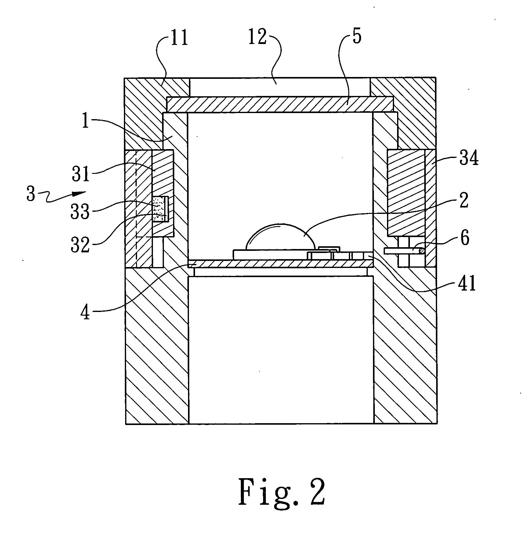
[0014]FIGS. 1-3 respectively shows an exploded perspective view, a sectional view, and a perspective view of a preferred embodiment of a lighting device with a magnetic switch according to the present invention. Referring to FIGS. 1-3, the lighting device comprises a main body 1, a switching unit 3, at least a magnetic piece 33, a circuit board 4, at least a magnetic induction element 41, and a lighting element 2.

[0015]The switching element 3 can be, but not limited to, a ring structure. The ring structure 3 includes an internal rotating ring 31 and an external rotating ring 34. The outer peripheries of the internal rotating ring 31 are provided with plural protrusions and the inner peripheries of the external rotating ring 34 are provided with plural recesses corresponding to the protrusions. The external rotating ring 34 is connected with the internal rotating ring 31 by the engagement of the protrusions and the recesses. Besides, the ring structure 3 is further provided with a ho...


PUM


Abstract

A lighting device with a magnetic switch is disclosed, wherein plural magnetic fields are produced by utilizing a magnetic piece and a magnetic induction element together with a ring structure to form circuits equivalent to functional keys and make a lighting element produce plural induction effects under the control of a magnetic induction element via a circuit board, so that the lighting device can be operated easily.

Description

BACKGROUND OF THE INVENTION[0001]1. Field of the Invention[0002]The present invention relates to a lighting device with a magnetic switch and, more particularly, to a lighting device with a magnetic switch wherein plural magnetic fields are produced as a result of the relative change of the positions of a magnetic piece and a magnetic induction element to make a lighting element produce plural induction effects under the control of the magnetic induction element via a circuit board.[0003]2. Description of the Prior Art[0004]With respect to multifunctional portable lighting devices such as a flashlight, it is difficult to design the lighting devices where all setting and operations can be controlled by one key because of size, appearance, and waterproofing problems. Even the design of multiple keys are applied, it is necessary to add many extra waterproof structures. Besides, some lighting devices are designed to have multiple keys controlled by pressing the keys at intervals and in ...

Claims


Application Information

Patent Timeline
IPC IPC(8): F21V23/04H05B44/00
CPCF21V31/00F21V23/0414H01H36/00
Inventor CHIA-LI, CHENJUI-HUANG, TSENG
Owner DOSUN SOLAR TECH
Why Eureka
Try Eureka