Pool cleaner control subsystem

a technology of control subsystem and pool cleaner, which is applied in the direction of filtration separation, cleaning using liquids, separation processes, etc., can solve the problems of increasing the time, increasing the time, and excessive body rotation, so as to minimize the formation of conduit tangles, maximize the time spent cleaning, and avoid the effect of increasing the number of incidents of conduit tangles

Inactive Publication Date: 2008-03-13
HENKIN LABY
View PDF17 Cites 40 Cited by
  • Summary
  • Abstract
  • Description
  • Claims
  • Application Information

AI Technical Summary

Benefits of technology

[0006] The present invention is directed to a method and apparatus for operating a pool cleaner body in a manner to maximize the time spent on cleaning relative to the time spent on repositioning. More particularly, the invention is directed to a control subsystem for operating a cleaner body to enable it to primarily travel in a forward direction (i.e., forward state) along a travel path but operable also in a backup / redirect state to translate and / or rotate the body to enable it to escape from obstructions while also minimizing the formation of conduit tangles. A control subsystem in accordance with the invention is configured to perform repositioning operations without increasing incidents of conduit tangling by: 1—avoiding an excessive rotation of the body, e.g., approximately 180° or more, when attempting to free the body from an obstruction; and / or 2—avoiding the initiation of a timed repositioning operation while the body is transitioning between a travel path at the wall surface and a travel path at the water surface.
[0008] In a preferred control subsystem embodiment, the magnitude, or effectiveness, of each succeeding redirect action in a reposition operation is progressively increased. For example, an initial redirect action can apply the repositioning force FR for a first interval (e.g., about four seconds) to rotate the cleaner body approximately 90° to redirect it for forward motion along a different travel path. Then a second redirect action can apply the force FR for a second interval (e.g., about six seconds) to rotate the body approximately 135° to redirect it for forward motion along a still different path. Additional redirect actions can be sequentially executed if necessary to apply the force FR for increasing durations. In most situations, the body will be free of the obstruction after the first and / or second redirect actions, thereby avoiding the necessity of a third redirect action and the additional rotation which can promote conduit tangles.

Problems solved by technology

This can occur, for example, when the body gets trapped by an obstruction.
Although the application of the repositioning force FR as described in said '878 patent is generally effective to free a cleaner body trapped by an obstruction, it has been observed that excessive body rotation can contribute to the formation of tangles, e.g., persistent coils and / or knots, in the conduit supplying power to the body.
The formation of such tangles is undesirable because tangles tend to impede the free travel of the body and increase the time dedicated to repositioning at the expense of the time available for cleaning.

Method used


Image

  • Pool cleaner control subsystem
  • Pool cleaner control subsystem
  • Pool cleaner control subsystem

Examples


Embodiment Construction

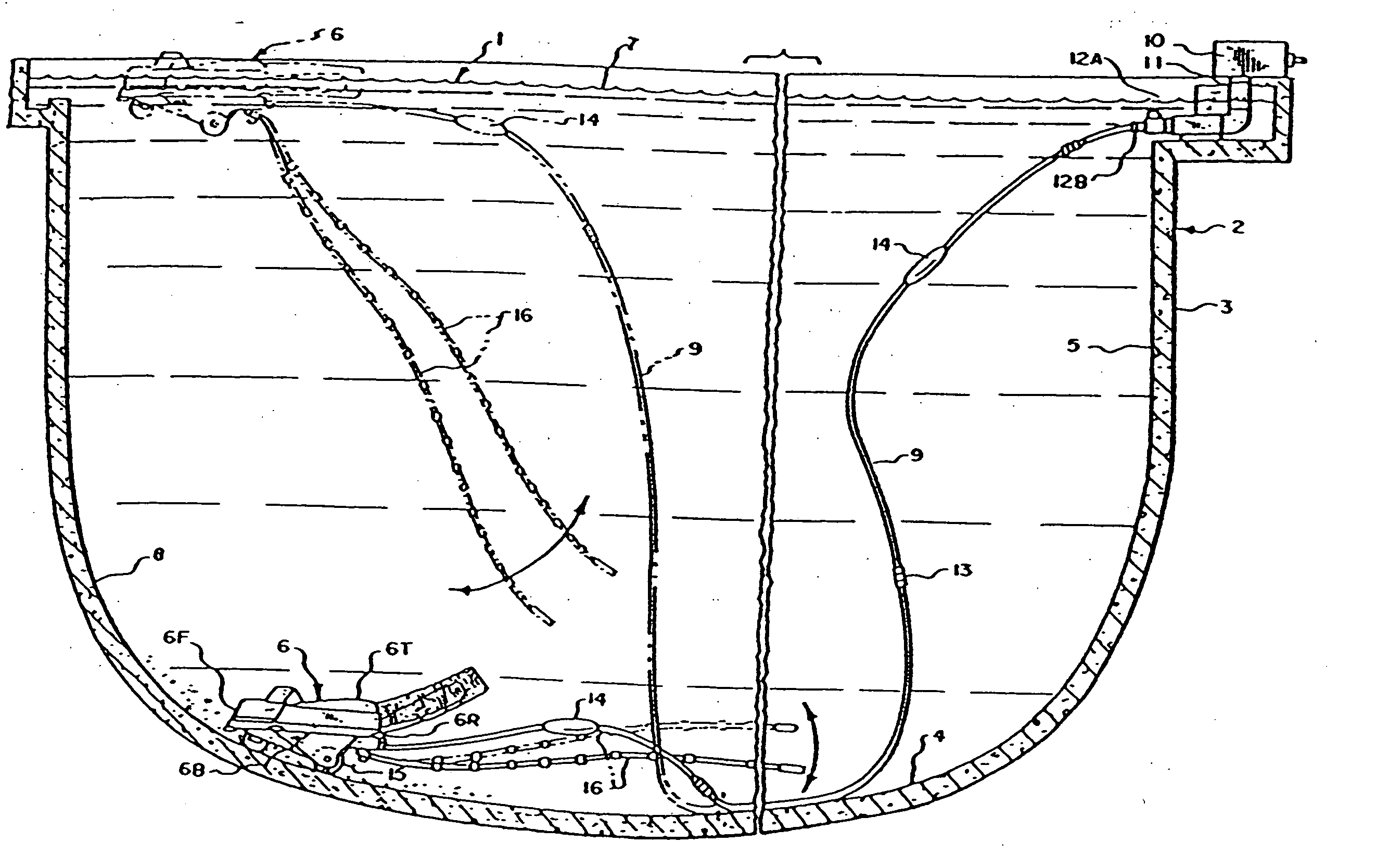
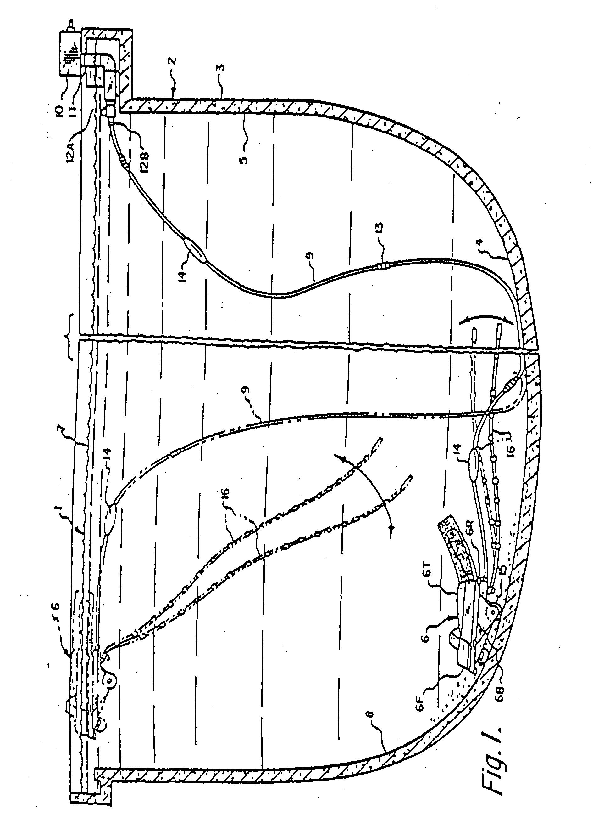
[0037] Attention is initially directed to FIG. 1 which duplicates a corresponding figure shown in U.S. Pat. No. 6,365,039. FIG. 1 illustrates a method and apparatus for cleaning a water pool 1 contained in an open vessel 2 defined by a containment wall 3 having a bottom 4 and side 5 portions. The apparatus includes a unitary structure or body 6 configured for immersion in the water pool 1 for selective operation to the interior wall surface 8 in a wall surface cleaning mode.

[0038] The unitary body 6 preferably comprises an essentially rigid structure having a hydrodynamically contoured exterior surface for efficient travel through the water pool 1. FIG. 1 depicts a heavier-than-water body 6 which in its quiescent or rest state typically sinks to a position (represented in solid line) proximate to the bottom of the pool 1. For operation in the water surface cleaning mode, a vertical force F+V is produced to lift the body 6 to proximate to the water surface 7 (represented in dash lin...


PUM

PropertyMeasurementUnit
angleaaaaaaaaaa
angleaaaaaaaaaa
propulsion force FPaaaaaaaaaa

Abstract

A method and apparatus for operating a pool cleaner body in a manner to maximize the time spent on cleaning relative to the time spent on repositioning. More particularly, the invention is directed to a control subsystem for operating a cleaner body to enable it to primarily travel in a forward direction (i.e., forward state) along a travel path but operable also in a backup / redirect state to translate and or rotate the body to enable it to escape from obstructions while also minimizing the formation of conduit tangles. The control subsystem is configured to perform reposition operations without increasing incidents of conduit tangling by: 1—avoiding an excessive rotation of the body, e.g., approximately 180° or more, when attempting to free the body from an obstruction; and / or 2—avoiding the initiation of a timed reposition operation while the body is transitioning between a travel path at the wall surface and a travel path at the water surface.

Description

RELATED APPLICATIONS [0001] This application is a CIP of PCT / US2006 / 017283 filed on 4 May 2006 which claims priority based on U.S. Application 60 / 678,499 filed on 5 May 2005. This application claims priority based on the aforecited applications which my reference are incorporated herein.FIELD OF THE INVENTION [0002] This invention relates generally to automatic swimming pool cleaners of the type which use a cleaner body for traveling through a water pool to clean the water and / or containment wall surfaces and more particularly to such cleaners in which the cleaner body is tethered to a conduit which supplies power (e.g., positive pressure water flow, negative pressure (i.e., suction) water flow, electricity, etc.) for propelling the body through the water pool. BACKGROUND OF THE INVENTION [0003] Well known automatic pool cleaners utilize a cleaner body coupled to a flexible conduit which supplies power to propel the body forwardly along a substantially random travel path though the ...

Claims


Application Information

Patent Timeline
Patent Type & Authority Applications(United States)
IPC IPC(8): E04H4/16B01D35/14
CPCE04H4/1654
Inventor HENKIN, MELVYN L.LABY, JORDAN M.
Owner HENKIN LABY
Why Eureka
Try Eureka