Heating Apparatus

Inactive Publication Date: 2008-03-13
NORITZ CORP
View PDF11 Cites 41 Cited by
  • Summary
  • Abstract
  • Description
  • Claims
  • Application Information

AI Technical Summary

Benefits of technology

[0074]The heating apparatus of the present invention has such advan

Problems solved by technology

Careful studies to solve the problems described above brought about a conclusion that drain considerably causes reduction of heat exchange efficiency of a latent heat exchanger.
Thus, heat of the combustion gas is used for revaporization of the drain, resulting in reduction of heat energy contributed to temperature rising of water in the heat exchanger.
In addition, when adhering to the surface of the latent heat exchanger, a large amount of drain decreases heat transfer to inside of the heat exchanger, resulting in substantial reduction of heat exchange efficiency.
Therefore, the latent heat exchanger for use in the conventional heating apparatus of the latent heat recovery type is obl

Method used


Image

  • Heating Apparatus
  • Heating Apparatus
  • Heating Apparatus

Examples


Embodiment Construction

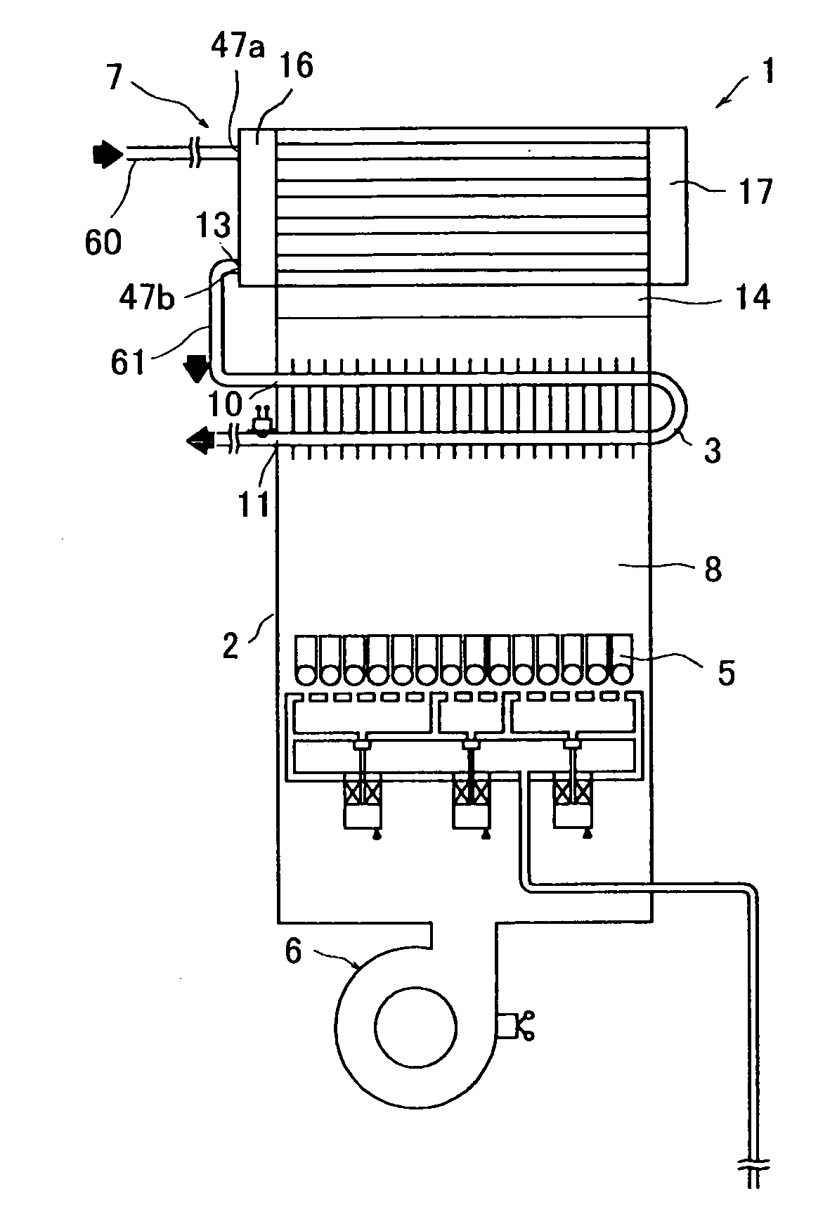
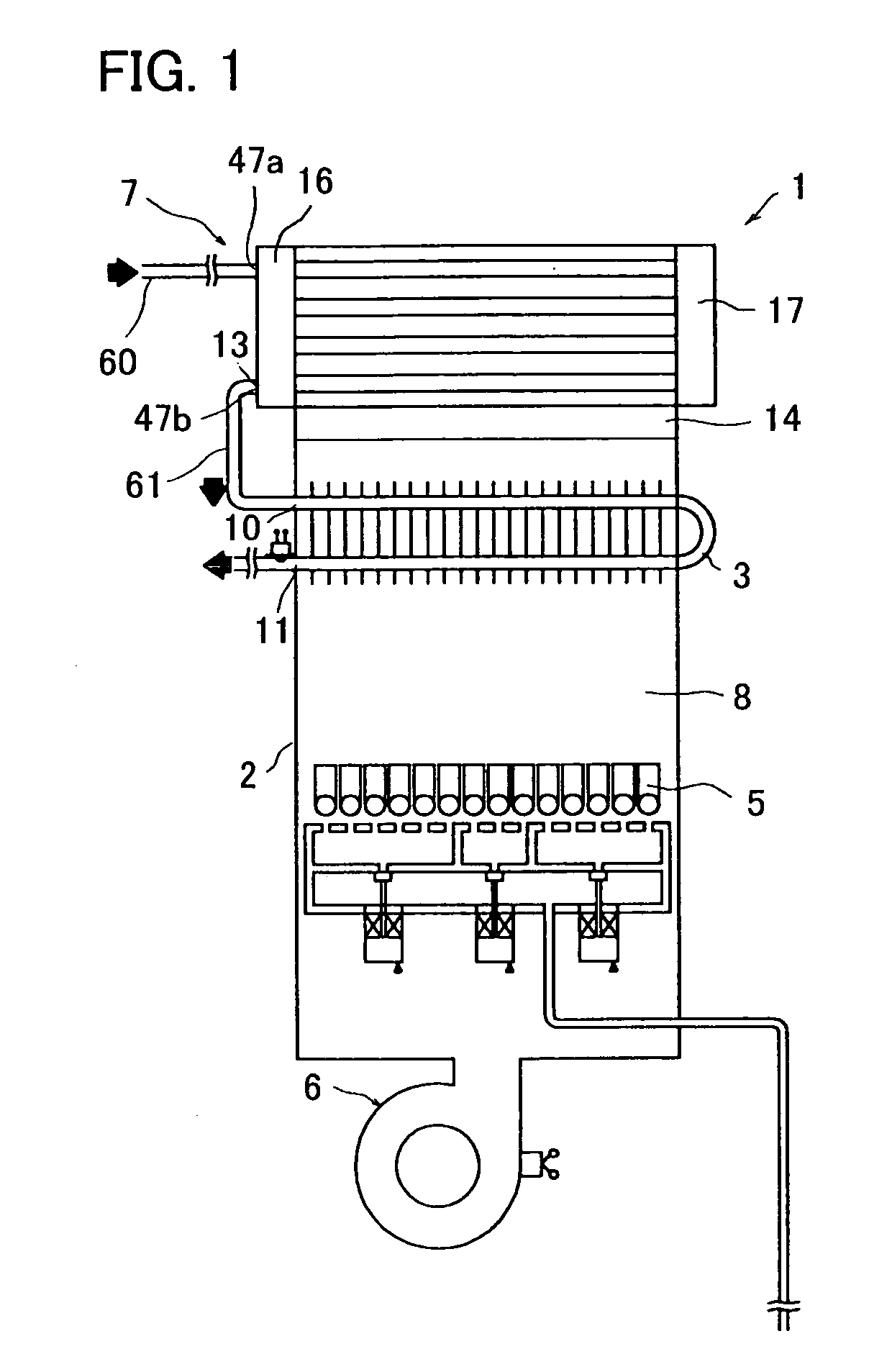
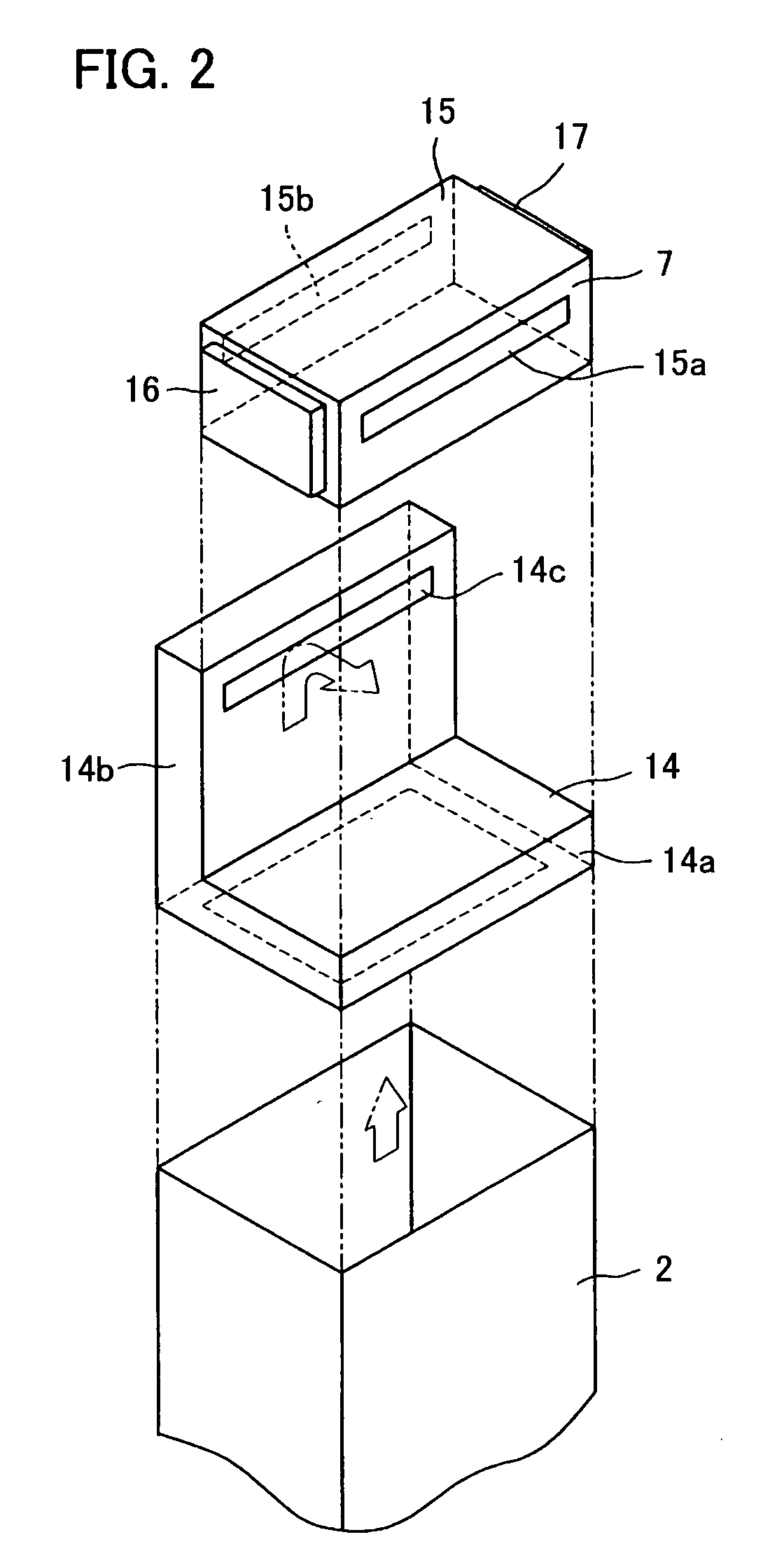
[0099]A combustion-type heating apparatus embodying the present invention will be described below in detail with reference to the accompanying drawings. FIG. 1 is a block diagram showing the heating apparatus of the present embodiment. FIG. 2 is an exploded perspective view showing the vicinity of a secondary heat exchanger of the heating apparatus shown in FIG. 1. FIG. 3 is a perspective view of the secondary heat exchanger and a gas-discharging member. FIG. 4 is an exploded perspective view of the secondary heat exchanger shown in FIG. 3. FIG. 5 is a cross-sectional view of the secondary heat exchanger as taken along A-A of FIG. 3. FIG. 6A is a schematic view showing arrangement of heat receiving tubes in the secondary heat exchanger shown in FIG. 3. FIG. 6B is a schematic view showing a modified example of arrangement of heat receiving tubes in the secondary heat exchanger shown in FIG. 3. FIGS. 7A and 8A each are a perspective view of a passage-forming member of the secondary he...


PUM


Abstract

A heating apparatus 1 includes a shell 2, a primary heat exchanger (sensible heat exchanger)3, a burner (combustion means) 5, and a fan 6. A secondary heat exchanger (latent heat exchanger) 7 has a plurality of heat receiving tubes 18 arranged in parallel between a pair of headers 16 and 17, the heat receiving tubes 18 being fixed to tube plates 20. The heat receiving tubes 18 are bare tubes without fins and are arranged across flow of combustion gas. The number of the tubes 18 arranged vertically is less than the number of the tubes 18 arranged horizontally.

Description

BACKGROUND OF THE INVENTION[0001]1. Technical Field[0002]The present invention relates to a heating apparatus using a burner, especially to a heating apparatus for heating water provided with a heat exchanger adapted to utilize (recover) latent heat of combustion gas.[0003]Herein, in the present application, the term “water” includes cold water and hot water, if not otherwise specified.[0004]2. Background Art[0005]A heating apparatus (also called a heat source equipment) using a burner for burning gas or liquid fuel is commonly used as heat source for a device such as a water heater or a bath heater. Recently, a combustion-type heating apparatus having higher heat efficiency than the conventional one has been desired in the point of view of energy saving or environmental conservation. Therefore, in order to achieve the above-mentioned object, a combustion-type heating apparatus provided with a plurality of heat exchangers or a heating apparatus of the combustion type referred to as ...

Claims


Application Information

Patent Timeline
IPC IPC(8): F24D12/02F24H1/14F24H1/40F24H8/00F24H9/14F28D7/00
CPCF24H1/40F24H8/00F24H9/14F24H1/46Y02B30/102F24H9/148F28D7/00Y02B30/00
Inventor OOTOMO, ICHIROASAKURA, HIROSHIHORI, TOSHIHIROTAKEDA, NOBUHIROKIMURA, KAZUHIROTSUTSUMI, AKIRAFUJITA, TAKAYASUMORIKAWA, MASAKUNI
Owner NORITZ CORP
Why Eureka
Try Eureka