Apparatus for Driving a Display

Inactive Publication Date: 2008-03-13
HIMAX TECH LTD
View PDF8 Cites 7 Cited by
  • Summary
  • Abstract
  • Description
  • Claims
  • Application Information

AI Technical Summary

Benefits of technology

[0008]Still another objective of the present invention is to provide an apparatus for dr

Problems solved by technology

Since the Vcom voltage generation circuit and the Gamma voltage generation circuit are set in th

Method used


Image

  • Apparatus for Driving a Display
  • Apparatus for Driving a Display
  • Apparatus for Driving a Display

Examples


Example

[0019]In order to make the illustration of the present invention more explicit and complete, the following description is stated with reference to FIGS. 3 through 5.

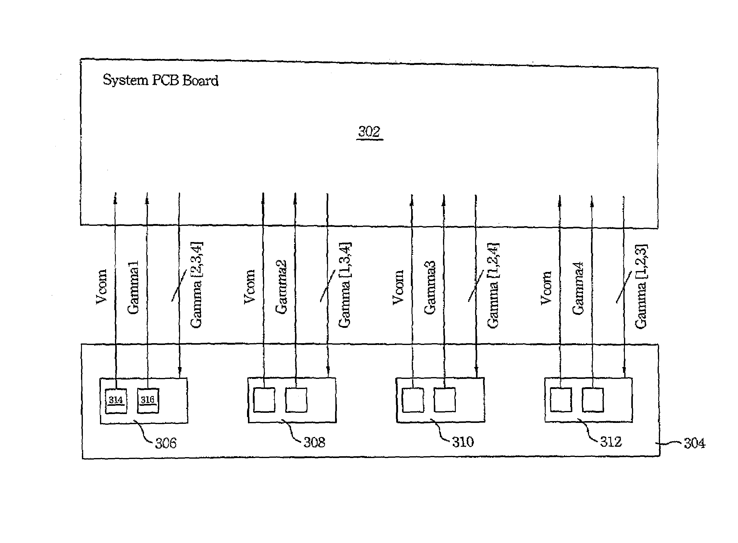
[0020]Reference is made to FIG. 3 illustrating a diagram of driving system according to the source driver circuit / chip of the preferred embodiment of the present invention. Each source driver chip receives pixel values (not shown) and outputs driving voltages corresponding to the pixel values according to a plurality of Gamma voltages. As shown in FIG. 3, a Vcom voltage generation circuit 314 and a Gamma voltage generation circuit 316 are both located in a source driver chip 306 in the preferred embodiment of the present invention. The Vcom voltage generation circuit 314 and the Gamma voltage generation circuit 316 generate a Vcom voltage and a Gamma voltage, respectively. Furthermore, the source driver chips (306, 308, 310, 312) also generate and send out at least one Gamma voltage, respectively, and receive other Gamma...


PUM


Abstract

The present invention discloses an apparatus for driving a display in which each pixels of the display receives a driving voltage and a common voltage, and a luminance of each pixel is determined by a difference between the received driving voltage and the common voltage. The apparatus comprises a plurality of source driver chips, each of which receives a pixel value and generates the driving voltage corresponding to the pixel value according to a plurality of Gamma voltages. The common voltage is generated by at least one of the source driver chips.

Description

FIELD OF THE INVENTION[0001]The present invention relates to a driving apparatus, and more particularly, to an LCD (Liquid Crystal Display) driving apparatus having gamma or common voltage generation circuits integrated into source drivers.BACKGROUND OF THE INVENTION[0002]An LCD driving system must include circuits for generation of a common voltage and a group of gamma voltages. Each of the pixels of the LCD panel receives a driving voltage and the common voltage, and a voltage difference therebetween determines the orientation of liquid crystals and therefore the luminance of the pixel. The driving voltages are generated by source drivers. Each source driver receives a pixel value and selects one of the gamma voltages as the driving voltage corresponding to the received pixel value.[0003]FIG. 1 shows a conventional common voltage (denoted as Vcom voltage hereinafter) generation circuit. The conventional Vcom voltage generation circuit is set in a system PCB board. Strings of resis...

Claims


Application Information

Patent Timeline
IPC IPC(8): G09G3/36
CPCG09G2320/0276G09G3/3655
Inventor CHANG, CHIN-TIENCHEN, YING-LIEHBU, LIN-KAI
Owner HIMAX TECH LTD
Why Eureka
Try Eureka