Heat exchange piece of moisture removal device, moisture removal device and clothes dryer

A technology for heat exchange parts and clothes dryers, which is applied in the fields of moisture removal devices, heat exchange parts, and clothes dryers. Optimized design, increased space, improved heat transfer effect

Pending Publication Date: 2022-03-29
YUNMI HULIAN TECH (GUANGDONG) CO LTD
View PDF13 Cites 0 Cited by
  • Summary
  • Abstract
  • Description
  • Claims
  • Application Information

AI Technical Summary

Problems solved by technology

[0003] At present, the clothes dryers on the market are heated by heaters to form hot air, and the hot air is passed into the drying drum through the fan. The hot air can take away the moisture on the surface or inside of the wet clothes, and then dry the wet clothes, and the formed damp heat The air is discharged from the air outlet of the inner cylinder. If the hot and humid air discharged from the inner cylinder is directly discharged to the outside of the dryer, it will have a great impact on the humidity and temperature of the environment where the dryer is located.
Existing clothes dryers will dehumidify and cool the hot and humid air. Cooling water is usually used to cool the hot and humid air. In order to maintain a certain cooling effect, the cooling channel used to accommodate the cooling water is designed as a curved structure. Take up a lot of space

Method used


Image

  • Heat exchange piece of moisture removal device, moisture removal device and clothes dryer
  • Heat exchange piece of moisture removal device, moisture removal device and clothes dryer
  • Heat exchange piece of moisture removal device, moisture removal device and clothes dryer

Examples


Embodiment 1

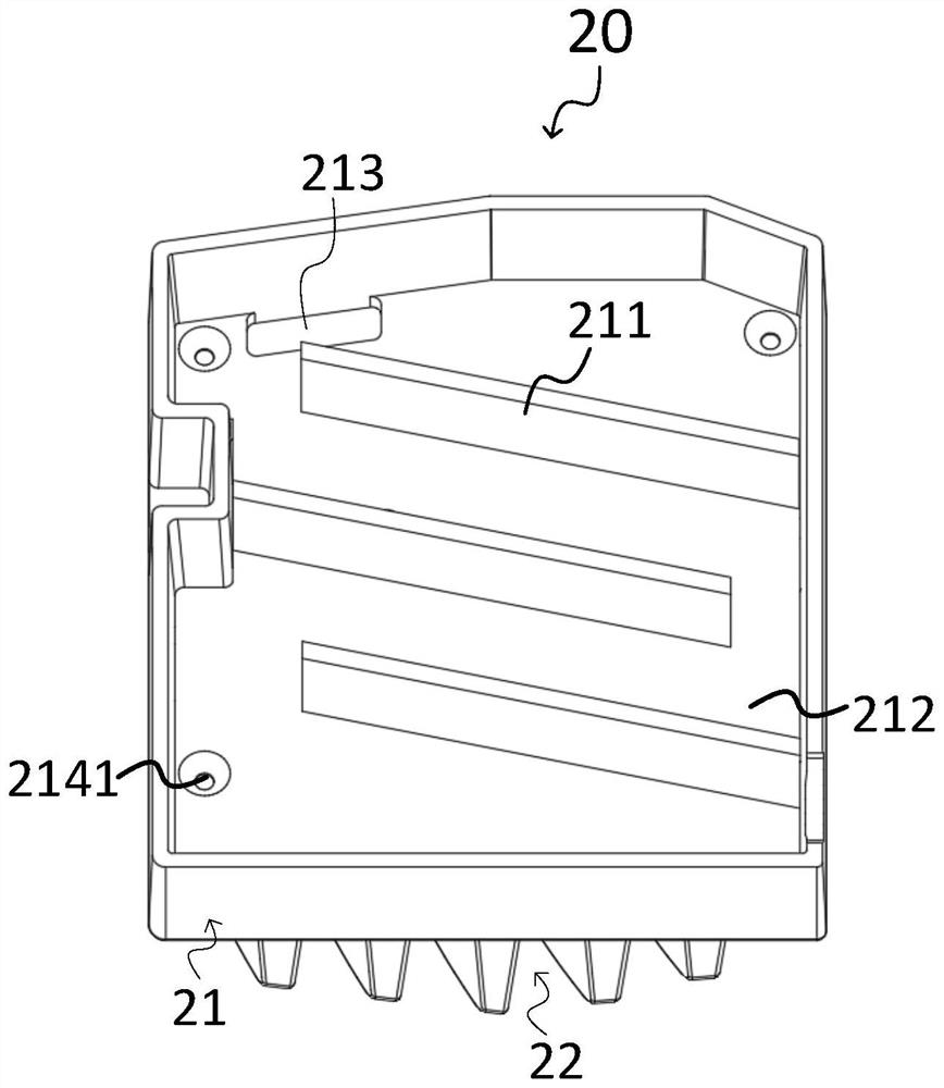
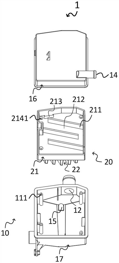
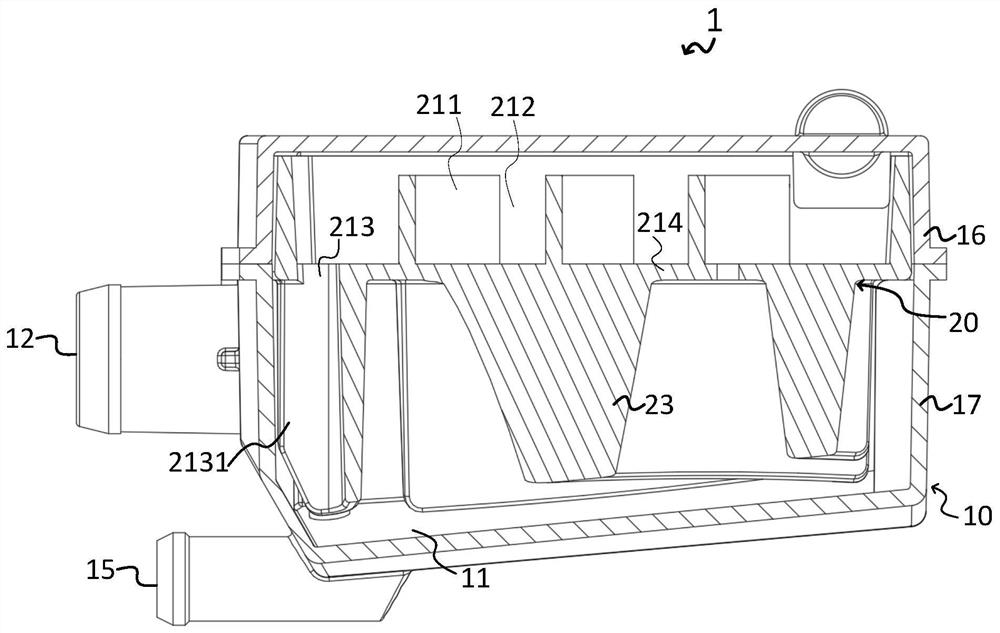
[0045] The present invention provides a heat exchange element for a moisture removal device, such as figure 1 , figure 2 As shown in the figure, it includes a heat exchange element body 20 arranged on the body 1 of the moisture removal device. The heat exchange element body 20 is provided with a cooling part 21 through which a cooling medium is introduced, so as to exchange heat with the moist and hot air contacting the cooling part 21; the cooling part 21 It includes a cavity and a baffle plate 211; the baffle plate 211 is arranged in the cavity to form a cooling channel 212 for the cooling medium to pass through together with the inner contour of the cavity; wherein,

[0046]The baffle 211 is a heat-conducting sheet with thermal conductivity; at least one baffle 211 is obliquely connected to the inner wall of one side of the cavity to increase the contact area with the cooling medium contained in the cooling channel 212 and improve the distance between the baffle and the co...

Embodiment 2

[0064] The invention provides a dehumidification device for a clothes dryer, such as figure 2 As shown, it includes a dehumidification device body 1 arranged in the clothes dryer body, and the dehumidification device body 1 includes:

[0065] The housing 10 is provided with a cavity 11 for accommodating the heat exchange element body 20, for accommodating the heat exchange element body 20, and forming a temporary storage space for moist and hot air. After the moist and hot air enters the cavity 11, due to the contour of the cavity 11 The restraint of the damp and hot air reduces the flow speed of the hot and humid air, so that the hot and humid air temporarily gathers in the cavity 11 to contact the body 20 of the heat exchange element in the cavity 11;

[0066] The heat exchange element body 20 described above is used to absorb the heat of the hot and humid air in the cavity 11;

[0067] The humid and hot air generated by the drying drum of the clothes dryer body enters the c...

Embodiment 3

[0083] The present invention provides a clothes dryer, which includes a clothes dryer body for performing drying, and the clothes dryer body includes the above-mentioned moisture removal device body 1 of a moisture removal device for a clothes dryer. The clothes dryer body includes a box body and a clothes dryer; the clothes dryer and the body 1 of the dehumidification device are all arranged in the box body. The humid and hot air in 11 is cooled and dehumidified and the air is discharged out of the box. When the dryer body executes the drying procedure, the hot and humid air in the drying drum passes into the cavity 11 from the air inlet 12, and after the cooling part 21 absorbs heat and cools, the moisture in the hot and humid air is condensed and removed, and then discharged from the air outlet 13. outside the box. The cooling medium after absorbing heat in the cooling channel 212 is discharged into the cavity 11 from the cooling medium outlet 213, and together with the co...


PUM


Abstract

The invention provides a heat exchange assembly for a moisture removal device. A heat exchange piece body is provided with a cooling part; the cooling part comprises a containing cavity and a baffle; the baffle is arranged in the containing cavity so that the baffle and the inner contour of the containing cavity can jointly form a cooling channel for a cooling medium to pass through. Wherein the baffle plate is a heat-conducting sheet; at least one baffle is obliquely connected to the inner wall of one side of the containing cavity so as to increase the contact area between the baffle and the cooling medium in the containing cavity. The invention further provides a moisture removal device and a clothes dryer. The baffle and the inner contour of the containing cavity jointly form a cooling channel for a cooling medium to pass through, the space of the cooling channel is enlarged, and therefore the heat exchange effect is improved, and miniaturization design of the cooling part is facilitated. At least one baffle is obliquely connected to the inner wall of one side of the containing cavity, the length of the baffle capable of being contained in the containing cavity is properly increased, then the contact area of the baffle and the cooling medium is increased to a certain degree, and the baffle is a heat conduction piece so as to accelerate the cooling part to transfer absorbed heat to the cooling medium in the cooling channel.

Description

technical field [0001] The invention relates to the technical field of household appliances, in particular to a heat exchange element of a moisture exhaust device, a moisture exhaust device and a clothes dryer. Background technique [0002] With the improvement of people's living standards, users' requirements for clothes dryers are not only cleaning. Due to weather factors, such as the rainy season, the drying time of clothes after washing is long, and some users also need clothes dryers that can dry clothes. . [0003] At present, the dryers on the market are heated by a heater to form hot air, and the hot air is passed into the drying drum through a fan. The air is discharged from the air outlet of the inner cylinder. If the hot and humid air discharged from the inner cylinder is directly discharged to the outside of the dryer, it will have a greater impact on the humidity and temperature of the environment where the dryer is located. Existing clothes dryers dehumidify ...

Claims


Application Information

Patent Timeline
Patent Type & Authority Applications(China)
IPC IPC(8): D06F58/20D06F58/24D06F58/00
CPCD06F58/20D06F58/24D06F58/00
Inventor 陈小平李宁宁杨骏崔天宇
Owner YUNMI HULIAN TECH (GUANGDONG) CO LTD
Why Eureka
Try Eureka