
Apparatus for Regulating Viscosity of Ink

a technology of ink viscosity and apparatus, which is applied in the direction of measuring devices, instruments, printing, etc., can solve the problems of inability to ensure accurate measurement, require too much measurement time, and malfunction of devices

Inactive Publication Date: 2008-03-13
NA JONG KAP
View PDF3 Cites 8 Cited by
  • Summary
  • Abstract
  • Description
  • Claims
  • Application Information

AI Technical Summary

Benefits of technology

[0006] Another object of the invention is to provide an apparatus for regulating viscosity of ink, which enables to measure an accurate viscosity of ink and also may allow a user to easily dissemble the apparatus and remove ink when a flow path is clogged due to the ink. Technical Solution
[0015] Preferably, a space for the ink to flow is formed between an outer circumference of the receptacle and an inner circumference of the housing, and the ink pressure regulating means keeps pressure of the ink constantly by controlling a flow rate of the ink flowing through the space.

Problems solved by technology

If viscosity of ink is changed as mentioned above, improvement of ink quality is not expected and a flow path in the printing device may be clogged due to the ink, causing malfunction of the device.
However, this method requires too much time for measurement, and cannot ensure accurate measurement since the measurement should be continued for the last drop of ink.
Most of all, since a worker measures viscosity of ink discontinuously and regulates it, the viscosity of ink cannot be maintained uniformly.
However, in this case, the ink flow path of the measurement device is frequently clogged due to the ink having relatively greater viscosity, and also this method does not allow a worker to easily separate and clean the measurement device.
Thus, a new measurement device should be frequently exchanged with an existing one, disadvantageously in terms of economy.

Method used


Image

  • Apparatus for Regulating Viscosity of Ink
  • Apparatus for Regulating Viscosity of Ink
  • Apparatus for Regulating Viscosity of Ink

Examples


Embodiment Construction

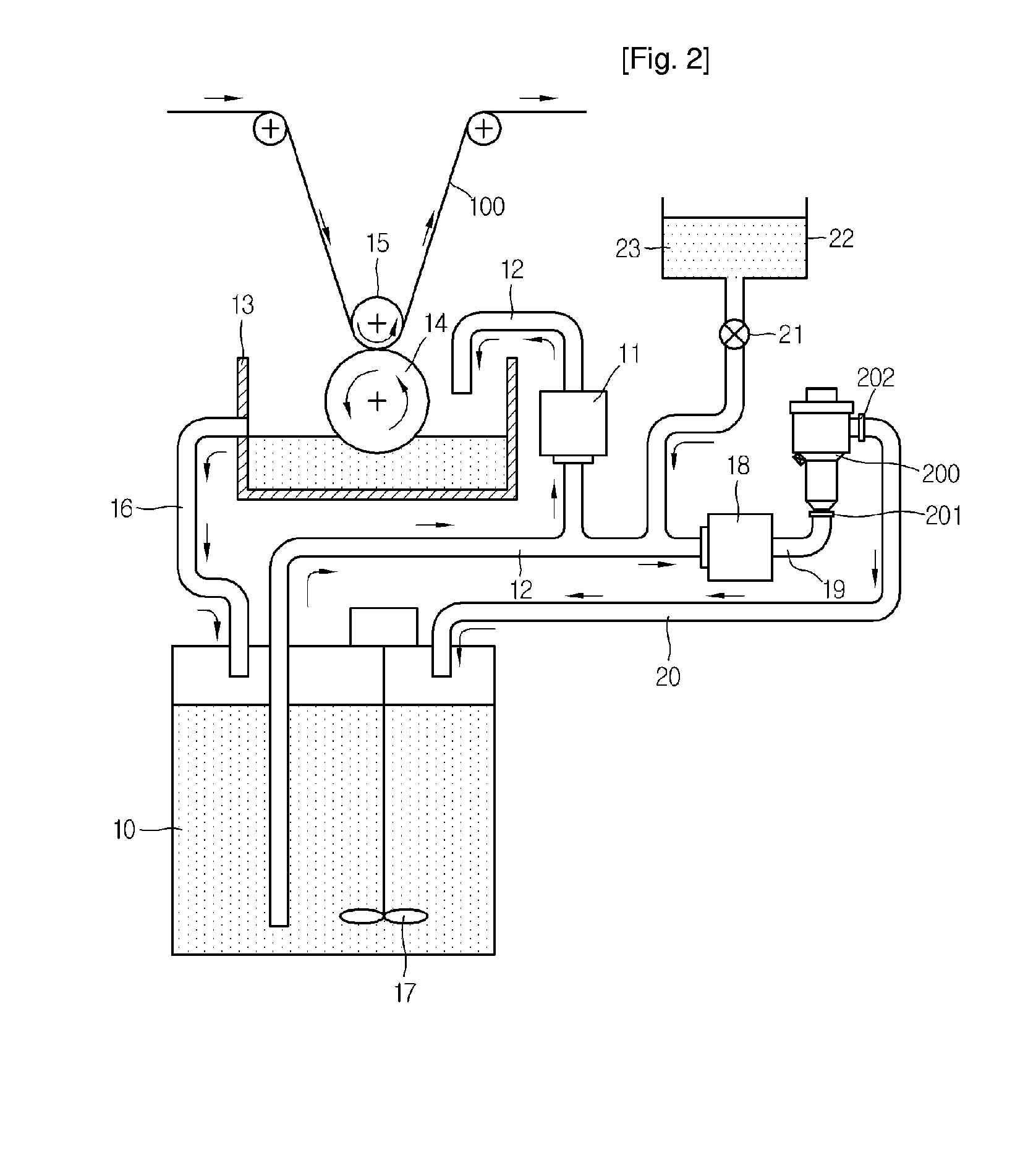
[0030]FIG. 2 is a schematic diagram showing a printing device adopting an apparatus for regulating viscosity of ink according to a preferred embodiment of the present invention.

[0031] Ink stored in a storage tank 10 is sent to a printing container 13 through a supply passage 12 by means of a driving force of a driving pump 11.

[0032] On the printing container 13, a printing roller 14 and a press roller 15 contacting with the printing roller 14 and rotating together with the printing roller 14 are installed.

[0033] An unprinted fabric 100 passes through the printing roller 14 and the press roller 15, and at this time the printing roller 14 gets wet with the ink contained in the printing container 13 to conduct a printing work. The ink in the printing container 13 returns to the storage tank 10 through a retrieving passage 16, thereby ensuring circulation. Reference numeral 17 denotes a stirrer for stirring the ink in the storage tank 10.

[0034] The ink viscosity regulating apparatus...


PUM


Abstract

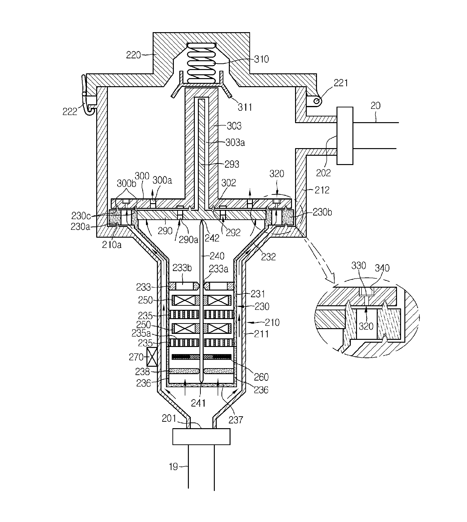
Disclosed is an apparatus for regulating viscosity of ink, which is installed on a flow path of ink in a printing device for regulation of ink viscosity. The apparatus includes a housing installed on the flow path and having an introduction hole and a discharge hole through which ink is introduced and discharged; a rotary shaft installed in the housing and to which at least one rotating fan is coupled to rotate along with flow of the ink; a sensed member having a sensed body at one end thereof and coupled to the rotary shaft to rotate together with the rotary shaft; and a sensor for sensing the sensed body.

Description

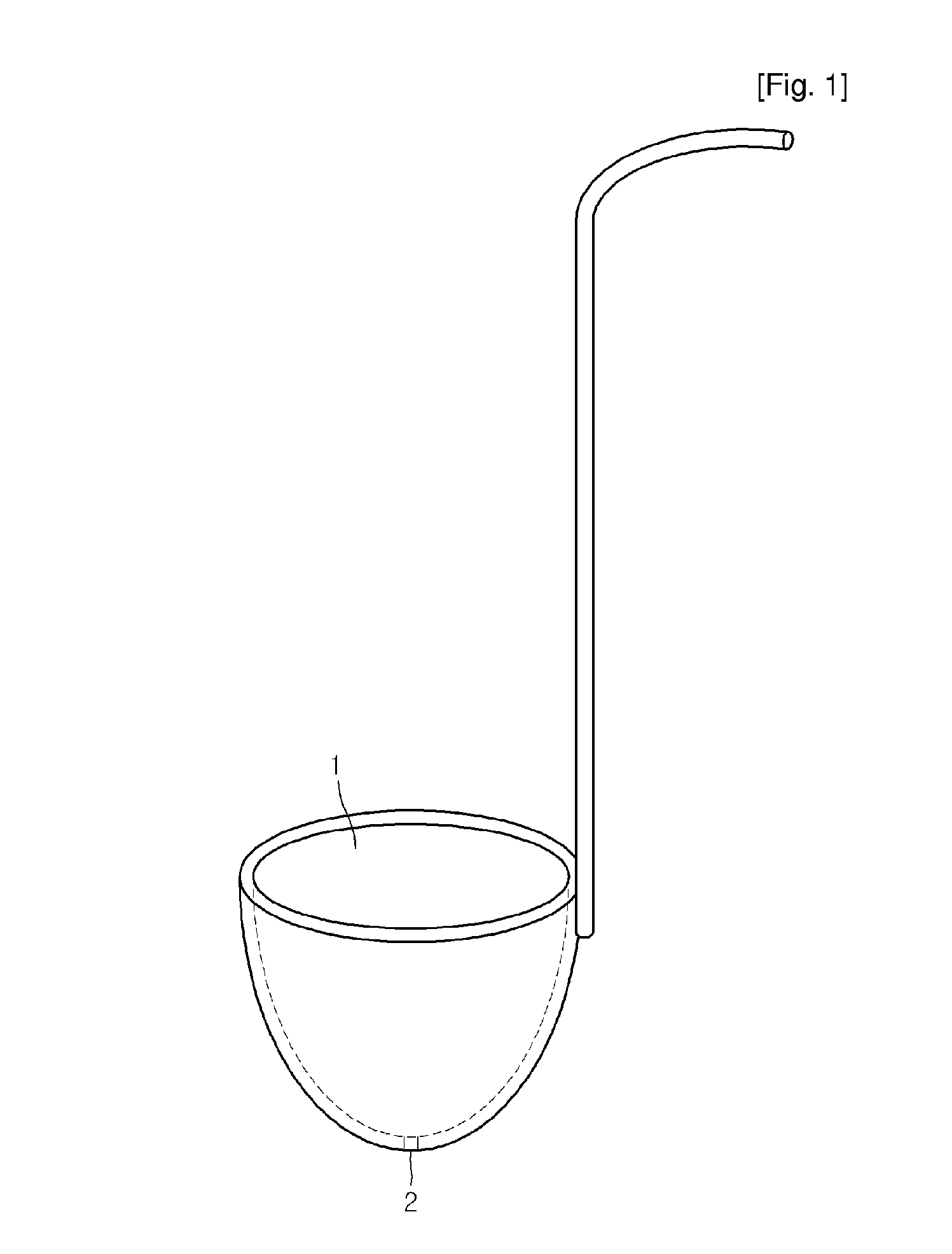
TECHNICAL FIELD [0001] The present invention relates to an apparatus for regulating viscosity of ink, and more particularly to an apparatus for regulating viscosity of ink used in a printing device within a predetermined range. BACKGROUND ART [0002] Viscosity of ink is very important to a printing device that prints a large amount of printed matters. Since ink contains volatile solution in itself, its concentration tends to become higher as time goes. If viscosity of ink is changed as mentioned above, improvement of ink quality is not expected and a flow path in the printing device may be clogged due to the ink, causing malfunction of the device. Thus, most printing devices need a means for suitably keeping viscosity of ink within a predetermined range. [0003] One of conventional ink viscosity measuring methods is depending much on a man ual work as shown in FIG. 1. That is to say, after ink is filled in a container 1 having a hole 2 of a certain size at its bottom, a time that the ...

Claims


Application Information

Patent Timeline
Patent Type & Authority Applications(United States)
IPC IPC(8): B41J2/195
CPCB41F31/005G01N11/14B41J2/195
Inventor NA, JONG-KAP
Owner NA JONG KAP
Learn More