Piezofan and heat sink system for enhanced heat transfer

a technology of enhanced heat transfer and heat sink, which is applied in the direction of machines/engines, positive displacement liquid engines, lighting and heating apparatus, etc., can solve the problem that the u.s. patent no. 4,498,851 does not provide any teaching on directing air flow

Active Publication Date: 2008-03-13
CONSUMER LIGHTING (U S) LLC
View PDF10 Cites 58 Cited by
  • Summary
  • Abstract
  • Description
  • Claims
  • Application Information

AI Technical Summary

Problems solved by technology

U.S. Pat. No. 4,498,851 does not provide any teaching for directing air flow generated by a piezoelectric fan where ducts and channels are desired.

Method used


Image

  • Piezofan and heat sink system for enhanced heat transfer
  • Piezofan and heat sink system for enhanced heat transfer
  • Piezofan and heat sink system for enhanced heat transfer

Examples


Embodiment Construction

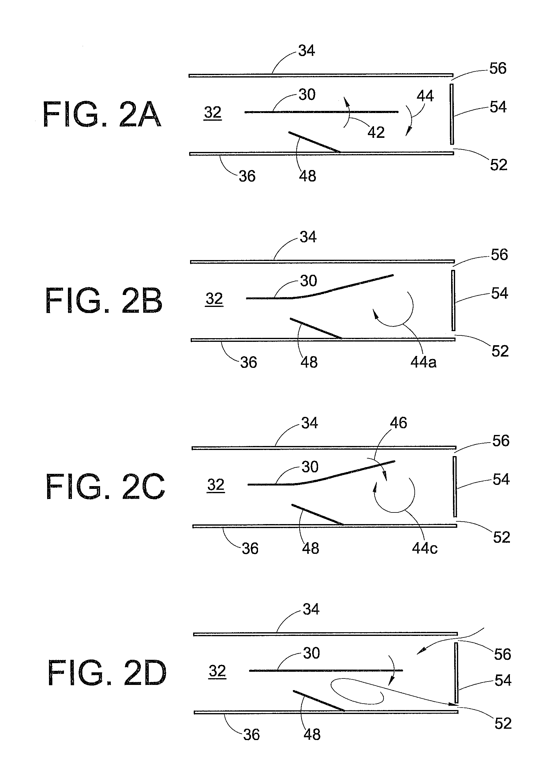
[0015]FIGS. 2A-2D depict a blade 30 of a piezoelectric fan disposed in a channel 32 defined by a first side wall 34, a second side wall 36 and a base wall (not numbered) that the side walls extend upwardly from. The blade is driven by a piezoelectric element (not shown), which will be described later. In FIG. 2A, the blade 30 of the piezoelectric fan is centered and moving upward as indicated by arrow 42, and air is being sucked toward the second wall 36 around the blade tip as indicated by arrow 44. The blade 30 nears its maximum stroke of its travel in FIG. 2B, leaving a nearly fully formed vortex 44a in its wake. The blade 30 then starts downwardly again in FIG. 2C as indicated by arrow 46. A fully formed vortex 44c is compressed against a constriction (formed by a constrictive member 48 extending into the channel 32 from the second side wall 36) and is expelled from an outlet 52 of the channel as seen in FIG. 2D as the blade 30 continues to move toward the second side wall 36. T...


PUM


Abstract

An electronic device having enhanced heat dissipation capabilities includes an electronic device, a heat sink, a channel, a piezoelectric element, and a blade. The heat sink is in thermal communication with the electronic device. The channel includes an inlet, an outlet and a constriction disposed along the channel between the inlet and the outlet. The heat sink defines at least a portion of the channel. The blade includes a free end and an attached end. The blade is disposed in the channel and connected to the piezoelectric element. The piezoelectric element is activated to move the blade side to side in the channel to create air vortices. The constriction in the channel and the blade cooperate with one another such that a vortex that is generated as the blade moves toward a first side of the channel is compressed against the first side of the channel and expelled towards the outlet of the channel.

Description

BACKGROUND[0001]Piezoelectric fans operate as a vortex shedding device. U.S. Pat. No. 4,498,851 nicely describes vortex shedding as a process where air is prevented from being sucked around a piezoelectric fan blade tip when its motion reverses. Vortex shedding is based on the fact that air displaced from the front of a moving blade rotates so rapidly that the air is unable to reverse its direction of rotation when the blade reverses its motion. If the rotation is not sufficiently rapid, the vortex can reverse its direction of rotation to be sucked around the blade tip instead of leaving the blade.[0002]The vortex shedding action is illustrated in FIGS. 1A-1I. In FIG. 1A, a blade 10 of a piezoelectric fan is centered and moving upward at maximum velocity as indicated by arrow 12, and air is being sucked downward around the blade tip as indicated by arrow 14. While this is happening, a previously shed vortex 16 is moving to the right below a center line 18 of the blade (the center li...

Claims


Application Information

Patent Timeline
Patent Type & Authority Applications(United States)
IPC IPC(8): H05K7/20
CPCF04D33/00
Inventor PETROSKI, JAMES T.
Owner CONSUMER LIGHTING (U S) LLC
Why Eureka
Try Eureka