System and method for convective heat transfer utilizing a particulate solution in a time varying field

a technology of convective heat transfer and particulate solution, which is applied in the direction of indirect heat exchangers, semiconductor/solid-state device details, lighting and heating apparatus, etc., can solve the problems of microelectronic components that are particularly susceptible to thermal management problems, heat transfer limitations and optimization, etc., and achieve high conductive, fast conduct heat directly from the wall, and superior thermal conductivity

Inactive Publication Date: 2007-02-22
UNITED STATES OF AMERICA
View PDF6 Cites 26 Cited by
  • Summary
  • Abstract
  • Description
  • Claims
  • Application Information

AI Technical Summary

Benefits of technology

[0016] In another exemplary embodiment, the slurry comprises particles that are affected by electric fields and a liquid used as the convective heat transfer medium. A time-varying electric field is produced in a fluid channel of the heat exchanger to cause the particles to be attracted to the walls of the fluid channel. The field would remain energized long enough to attract the particles to the walls and also allow the heat to be transferred to/from the particles. The particles are highly conductive and therefore are able to quickly conduct heat directly from the wall with their superior thermal conductivity. The particles are then released back into the fluid and transfer heat into/out of the bulk liquid. With an electric field utilized as the particle manipulative motive force, particle removal may be enhanced by: de-energizing the electric field that initially attracted the particle to the wall; and then energizing an electric field that is dis...

Problems solved by technology

Heat transfer limitations and optimization have been an engineering design constraint for decades.
More recently, cooling effectiveness has become a very important technical challenge and is one of the limiting factors in the further development of a range of military related disciplines including electronic, high-energy weapon and propulsion systems.
Microelectronic components are particularly susceptible to thermal management problem...

Method used


Image

  • System and method for convective heat transfer utilizing a particulate solution in a time varying field
  • System and method for convective heat transfer utilizing a particulate solution in a time varying field
  • System and method for convective heat transfer utilizing a particulate solution in a time varying field

Examples


Embodiment Construction

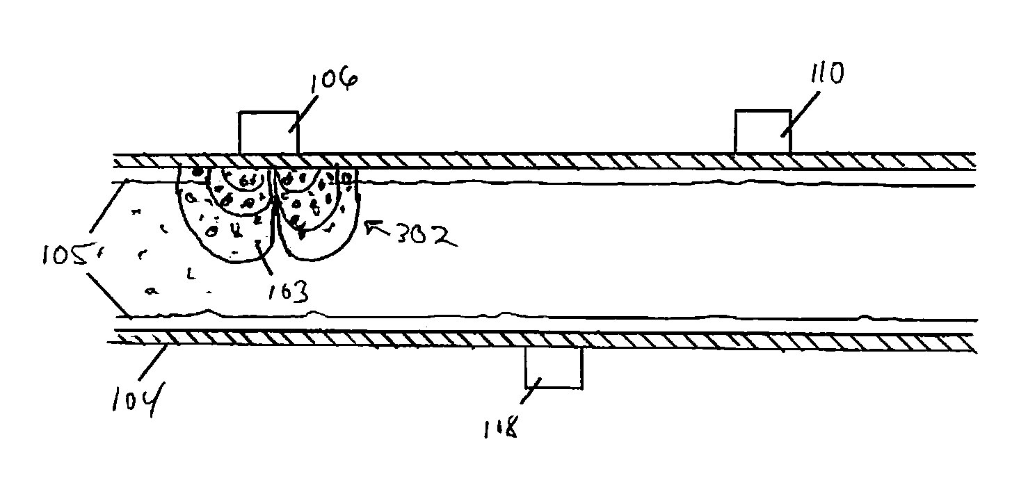
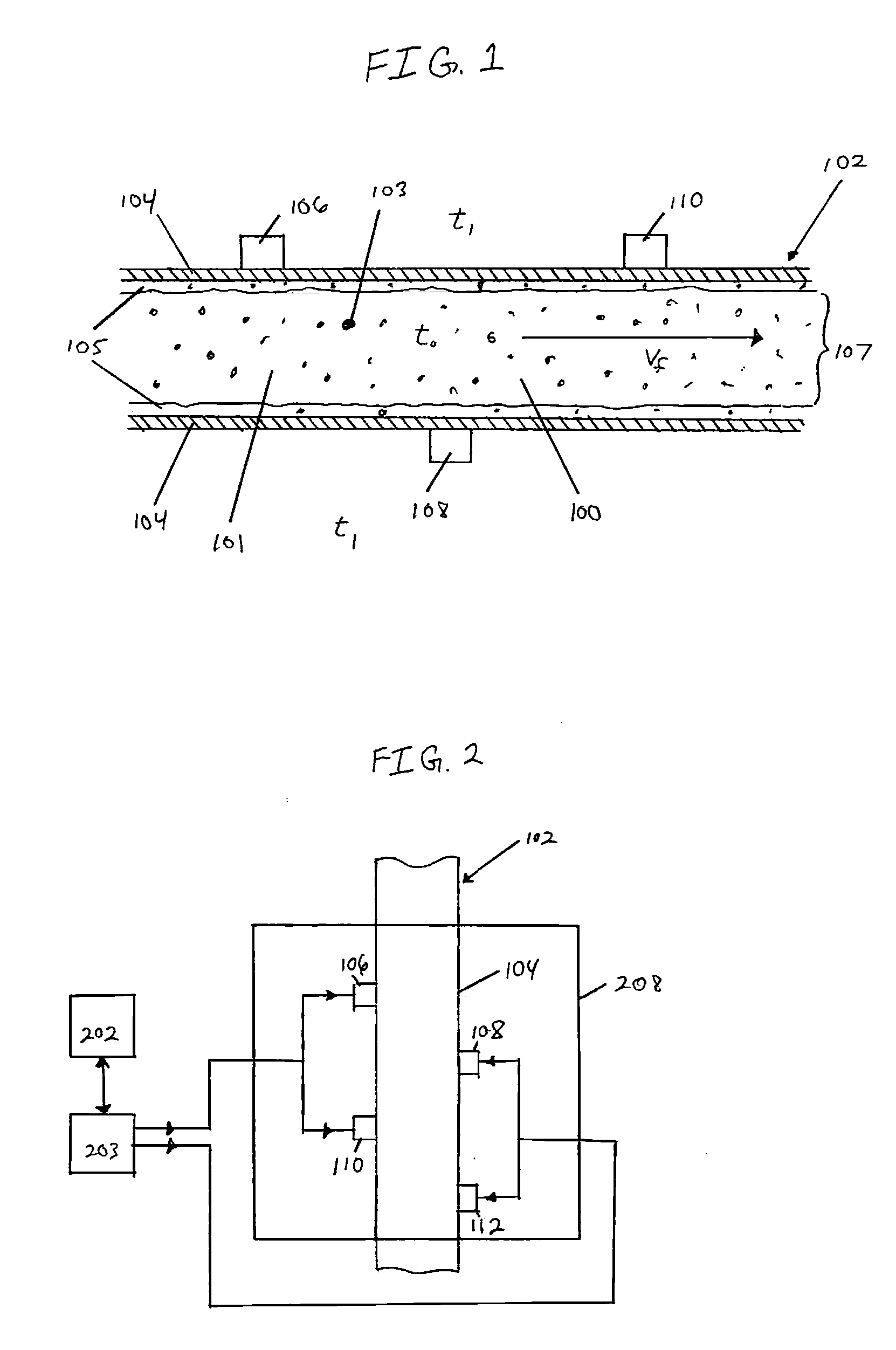
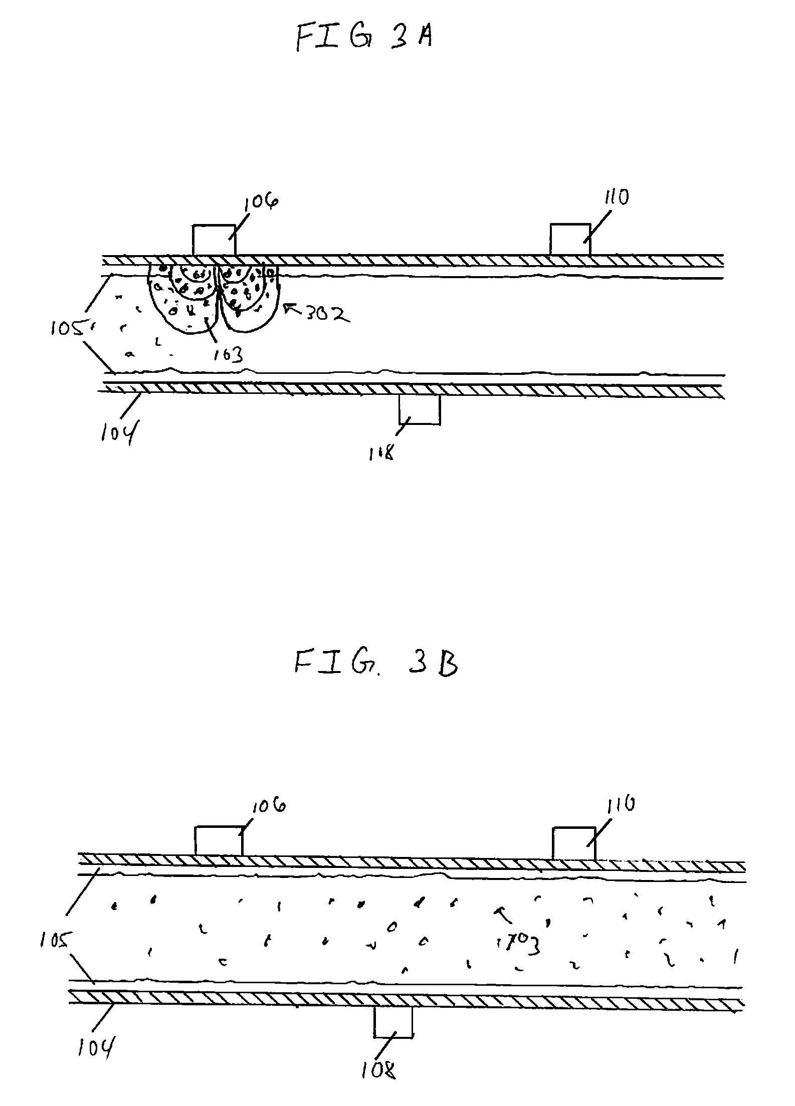
[0030]FIG. 1 illustrates a fluid channel 102, having a slurry 100 flowing therethrough, to be used in accordance with the present invention. Slurry 100 includes fluid 101 and particles 103 therein. Particles 103 may comprise any type of material or combination of materials that has a field-reactive property non-limiting examples of which include an electric and / or a magnetic field reactive property. Particles 103 possess greater thermal conductivity than fluid 101. Additionally, particles 103 may vary in size and shape and further need not be uniform. The size of particles 103 preferably should not be so large as to impede the flow of slurry 100 through fluid channel 102. In an exemplary embodiment, particles 103 are no larger than several nanometers. Further, in the presence of a field, particles 103 are capable of non-homogeneous distribution within fluid 101.

[0031] In operation, slurry 100 flows through fluid channel 102 creating a boundary layer 105 adjacent to a wall 104. Acco...


PUM


Abstract

A system combines the thermal conductivity characteristics of certain solids with the high specific heat values of appropriate fluids to enhance the overall heat transfer characteristics of a heat exchanger. The system comprises a fluid channel disposed in a heat exchanger unit with a slurry as the convective heat transfer medium. The slurry comprises an appropriate fluid with field reactive particles suspended therein. Field emitters are located along the walls of the fluid channel whereby the distribution of particles within the slurry is manipulated to achieve enhanced heat transfer characteristics.

Description

BACKGROUND [0001] Heat transfer limitations and optimization have been an engineering design constraint for decades. Thermal management has been a key consideration in the design and development of military hardware in the past century. More recently, cooling effectiveness has become a very important technical challenge and is one of the limiting factors in the further development of a range of military related disciplines including electronic, high-energy weapon and propulsion systems. Microelectronic components are particularly susceptible to thermal management problems and have become an integral component in most military systems. Many of these components cannot operate at elevated temperatures resulting in a thermal management system becoming a key consideration. [0002] Convective heat transfer is one way of addressing thermal management. Convective heat transfer is the heat transfer process that is executed by the flow of a fluid over a surface of a medium. Convective heat tra...

Claims


Application Information

Patent Timeline
IPC IPC(8): F28F13/12F28F27/00B29C47/88
CPCC09K5/10F28D2021/0029F28D2021/0098F28F13/00F28F13/02H01L2924/0002F28F13/16H01L23/473H01L2924/00
Inventor MURRAY, MARK M.
Owner UNITED STATES OF AMERICA
Why Eureka
Try Eureka