Apparatus and method for enhanced heat transfer

a technology of enhanced heat transfer and apparatus, applied in lighting and heating apparatus, electrical apparatus, cooling/ventilation/heating modification, etc., can solve the problems of noisy, unreliable, and generally very inefficient heat removal, and the conventional air-jet is not very useful for consumer products

Inactive Publication Date: 2006-03-09
INNOVATIVE FLUIDICS +1
View PDF21 Cites 25 Cited by
  • Summary
  • Abstract
  • Description
  • Claims
  • Application Information

AI Technical Summary

Problems solved by technology

Thermal management is recognized as a major challenge in the design and packaging of state-of-the-art integrated circuits in single-chip and multi-chip modules.
While air-cooling under natural convection conditions is the simplest possible way to cool a high heat flux device, high power dissipation requirements often necessitate the use of fans.
While fans have the capacity to move a substantial volume of air, they are noisy, unreliable and generally very inefficient in terms of the heat removed for a given rate of fluid flow.
However, conventional air-jets are not very useful for consumer products, due to requirements of pressure supplies and conduits for directing the air to the heat sink.
This makes design of the cooling system too complex and the cost of the cooling system too high for consumer product applications.
However, only some of the vast potential for synthetic jets in cooling applications has been explored.
A heretofore unaddressed need exists in the industry to address the aforementioned deficiencies and inadequacies.

Method used


Image

  • Apparatus and method for enhanced heat transfer
  • Apparatus and method for enhanced heat transfer
  • Apparatus and method for enhanced heat transfer

Examples


first embodiment

Operation of an Active Cooling Module

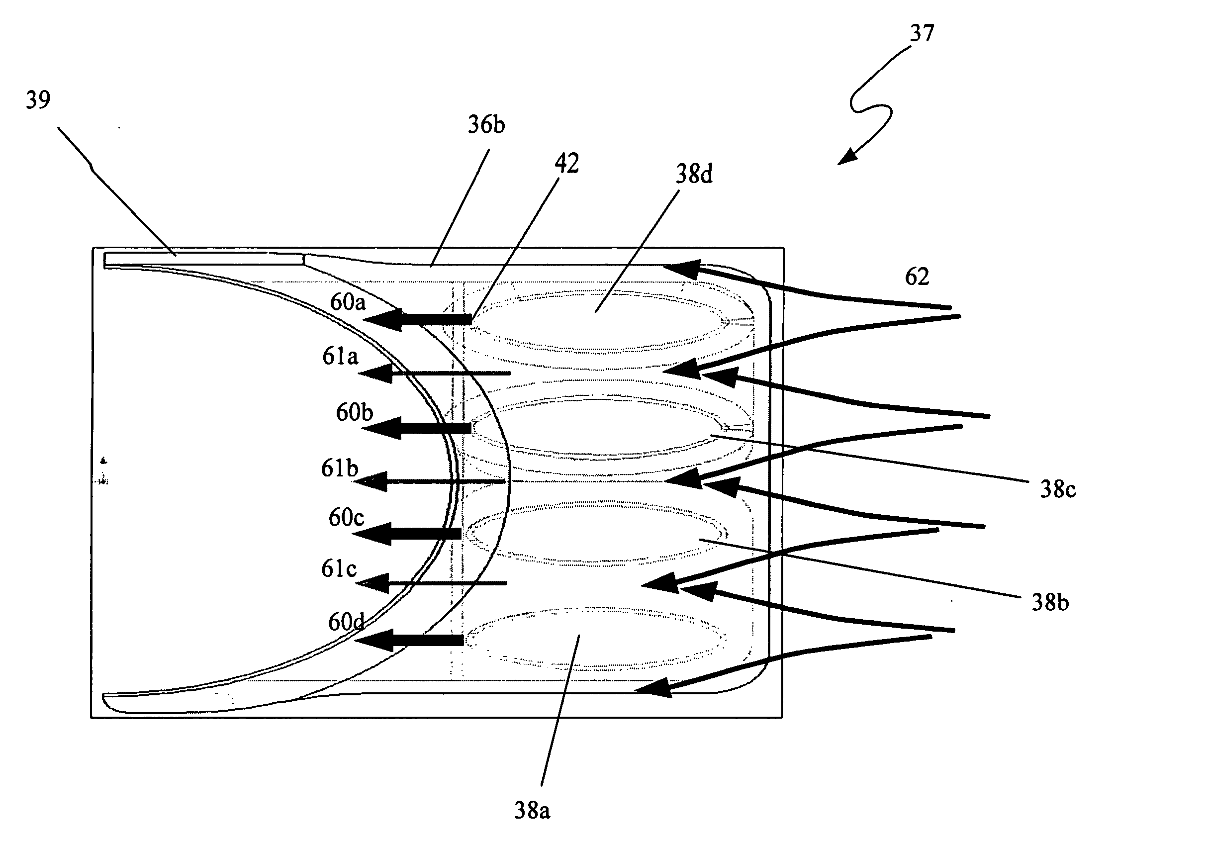
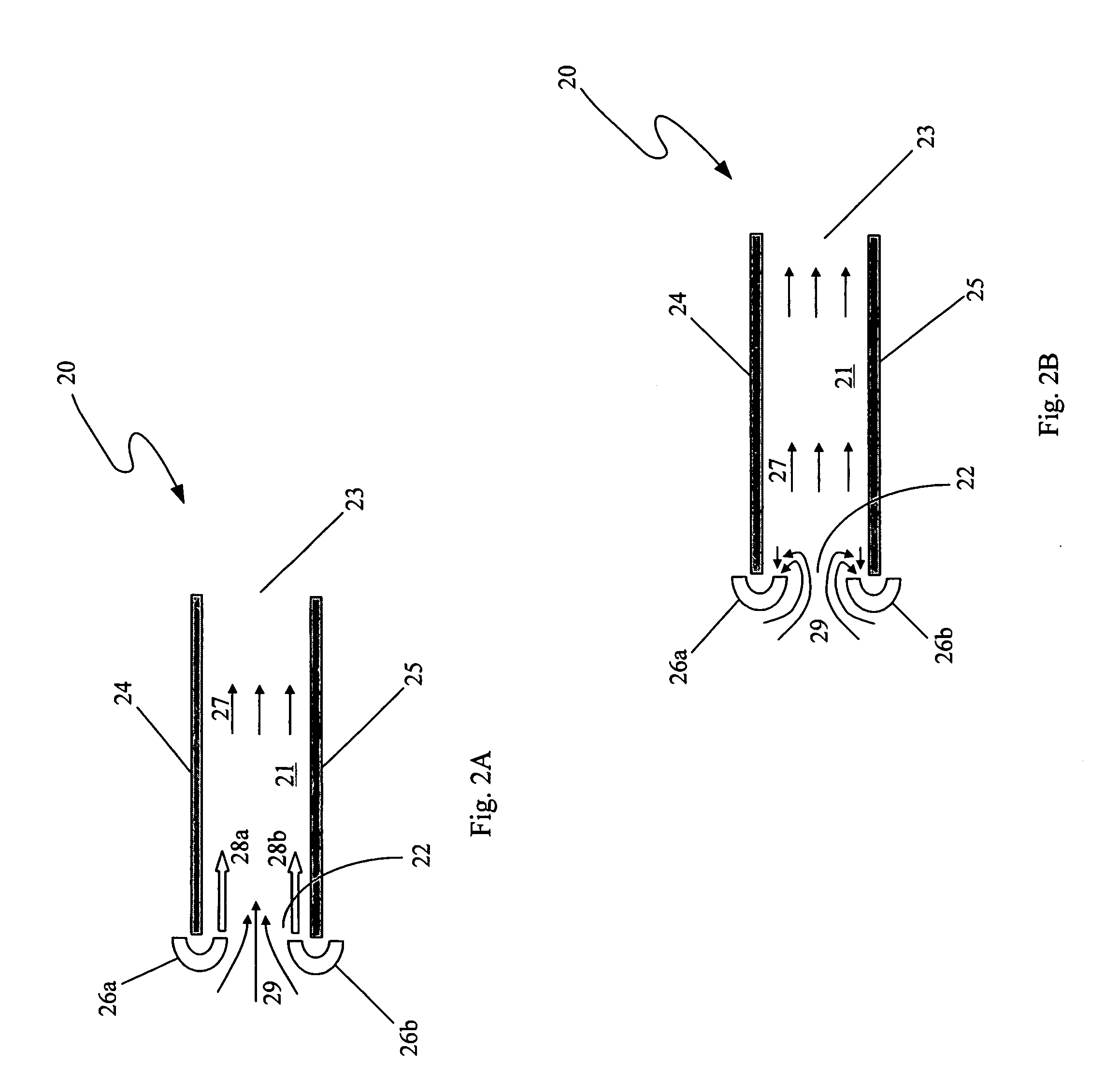
[0073] In operation, the synthetic jet matrix 32 creates the effect of a jet ejector 20, as discussed above in relation to FIGS. 2A and 2B, between adjacent fins 34 of the heat sink 31. Particularly, the control system causes the pistons in the actuator housings 35a, 36b to oscillate in periodic motion. Preferably, though not required, the pistons are caused to oscillate at a resonant frequency of the system 30.

[0074] The oscillation of the pistons causes the volumes of the chambers in the actuator housings 36a, 36b to be alternatively increased and decreased. As the chamber volume is increased, fluid is pulled in through the orifices 42 fluidically connected to the specific chamber having its volume increased. Then, as the volume of that chamber is decreased, due to the periodic motion of the piston 53, fluid is ejected from the orifices 42 connected to that chamber such that a synthetic jet stream of fluid is formed at the orifice 42. Basicall...


PUM


Abstract

One embodiment of the cooling module is implemented as a device having a heat sink and an integrated synthetic jet actuator. The heat sink is configured to have a channel and a jet distribution system associated with the synthetic jet actuator directs fluid flow into the channel of the heat sink. In operation, the fluid flow of this embodiment of the cooling module comprises a synthetic jet stream and ambient fluid entrained into the channel by the synthetic jet stream. The fluid flowing through the channel serves to a wall of the heat sink channel.

Description

CLAIM TO PRIORITY [0001] The present application claims the benefit of the filing date of U.S. Provisional Patent Application Ser. No. 60 / 607,187 filed on Sep. 3, 2004, which is hereby incorporated by reference herein.BACKGROUND [0002] 1. Technical Field [0003] The present invention is generally related to thermal management technology and, more particularly, is related to an apparatus and method for cooling heat-producing bodies or components using an integrated cooling module. [0004] 2. Description of the Related Art [0005] Cooling of heat-producing bodies is a concern in many different technologies. Particularly in microprocessors, the rise in heat dissipation levels accompanied by a shrinking thermal budget has resulted in the need for new cooling solutions beyond conventional thermal management techniques. This has led to an increased demand for advanced and robust cooling solutions with severe volume constraints. In the microelectronics industry, for example, advances in techn...

Claims


Application Information

Patent Timeline
Patent Type & Authority Applications(United States)
IPC IPC(8): H05K7/20
CPCY10S165/908H05K7/20172
Inventor GLEZER, ARIMAHALINGAM, RAGHAVENDRAN
Owner INNOVATIVE FLUIDICS
Why Eureka
Try Eureka