

Air cooled heat exchanger with enhanced heat transfer coefficient fins
a technology of heat exchanger and fin, which is applied in the direction of heat transfer modification, tubular elements, lighting and heating apparatus, etc., can solve the problems of high pressure drop penalty, high cost of pressure drop for airflow about the tube and fin, and the inability to increase the heat transfer ra
- Summary
- Abstract
- Description
- Claims
- Application Information
AI Technical Summary
Benefits of technology
Problems solved by technology
Method used
Image

Examples
Embodiment Construction
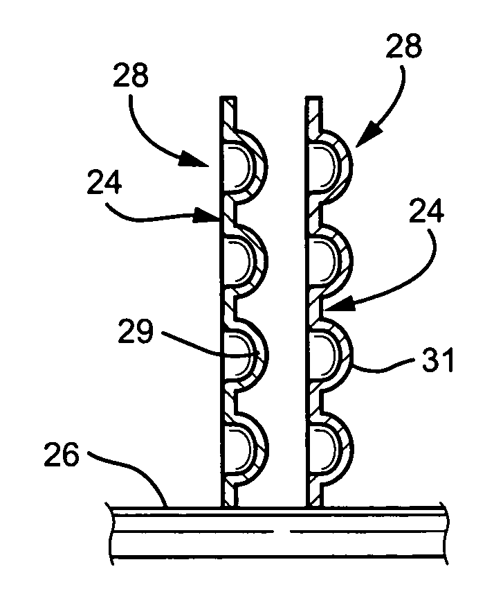
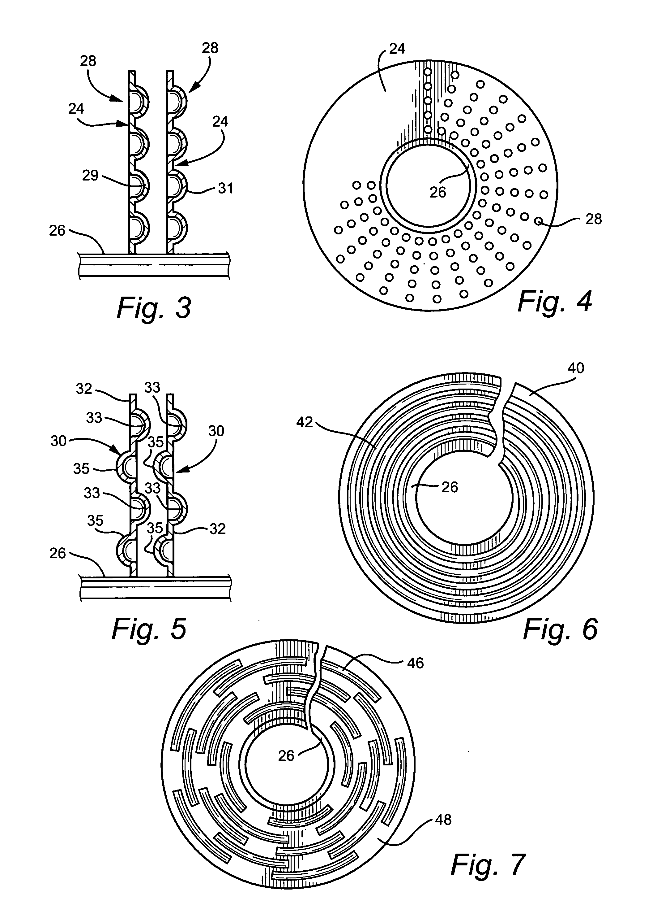
[0004]In one exemplary embodiment, the invention relates to a heat exchanger comprising: at least one tube for circulating a first fluid; a plurality of fins spaced one from the other about the at least one tube, the fins being in heat exchange relation between the first fluid flowing in the tube and a second fluid flowing about the fins and tube; at least one of the fins including a pattern of dimples or at least one groove about surfaces of the at least one fin to generate fluid vortices for heat transfer enhancement with minimum pressure loss as compared with smooth, undeformed fins.
[0005]In another exemplary embodiment, the invention relates to a heat exchanger comprising at least one tube for circulating a first fluid; a single continuous fin spirally wound about the one tube and being in heat exchange relation between the fluid flowing in the tube and a second fluid flowing about the fin and the tube; the single continuous fin including a mechanically pressed pattern of dimple...
PUM
 Abstract
Description
Claims
Application Information