Electrohydrodynamically (EHD) enhanced heat transfer system and method with an encapsulated electrode

a heat exchanger and electrohydrodynamic technology, applied in lighting and heating apparatus, cooling/ventilation/heating modification, electrical equipment, etc., can solve the problems of serious and vexing problems, affecting the performance of the thermal system, and removing dendritic crystals of ice, etc., to achieve low leakage current, low power consumption, and high efficiency

Inactive Publication Date: 2007-01-09
UNIV OF MARYLAND
View PDF17 Cites 26 Cited by
  • Summary
  • Abstract
  • Description
  • Claims
  • Application Information

AI Technical Summary

Benefits of technology

[0027]It is therefore an object of the present invention to provide an EHD-enhanced heat transfer technique free of short circuiting, capable of a high efficiency by using a strong electrical field without damaging of electrodes and breaking the fluid media, as well as having low leakage currents and therefore low power consumptions with an extended life of the electrodes and working fluids.

Problems solved by technology

It is known that frost formation in a beat exchanger seriously affects the performance of the thermal system.
This is an especially important problem in super market and food preservation refrigeration, food transportation refrigeration, as well as when applying heat pump systems to colder regions.
From the microscopic viewpoint, an important key issue is the removal of the dendritic crystals of ice from the heat transfer surface.
One of the serious problems of the heat exchangers used in commercial and industrial refrigeration systems is directed to frost forming on the heat exchanger surface whenever the surface temperature is below the freezing point of water.
The formation of frost in heat exchangers has been and continues to be a serious and vexing problem.
The frost formation negatively affects the heat transfer of the heat transfer system due to frost-induced additional heat transfer resistance at the surface and the reduction in free flow area between the working media and heat exchange surface.
The electrical field is highly non-uniform due to the angled shape of the spacing between the fins.
The non-uniform field thereby disrupts the disruptible layer adjacent to the heat exchange surface, thereby enhancing the heat exchange between the heat exchange surface and the working fluid.
Despite using the electrohydrodynamic enhancement of the heat transfer, the apparatus described in '155 patent, as well as the other EHD enhanced systems suffer from several drawbacks.
Such an arrangement may cause short circuiting between the electrode and the heat exchange surface if the heat transfer media is too conductive or if there are conductive impurities in the media which may be deposited between the electrode wire and the heat exchange surface (which is grounded for EHD purposes).
Another drawback is the possible current leakage, as well as ion recombination on the electrode wire, resulting in higher power consumptions for the EHD effect.
Additionally, electrochemical corrosion of electrodes may lead to premature breakdown of the electrodes and working media.
Disadvantageously to all above described EHD applications, these techniques use bare electrodes adjacent to the heat exchanging surface.
The bare electrodes are covered with condensed water, which is a good conductor, and as a result, these systems suffer high leakage currents, surface discharge and sparking, that substantially increases high voltage power consumption which may be up to 2 or 3 orders of magnitudes.
As a result, the achieved electrical field strength is low and the influence of the electrical field for augmentation of heat transfer processes is insufficient.
In both Publications, it has been shown that the effect of EHD technique is highly dependent on supporting a sufficient level of the electric field which in most cases is not possible with the bare electrode of the previously described EHD system.

Method used


Image

  • Electrohydrodynamically (EHD) enhanced heat transfer system and method with an encapsulated electrode
  • Electrohydrodynamically (EHD) enhanced heat transfer system and method with an encapsulated electrode
  • Electrohydrodynamically (EHD) enhanced heat transfer system and method with an encapsulated electrode

Examples


Embodiment Construction

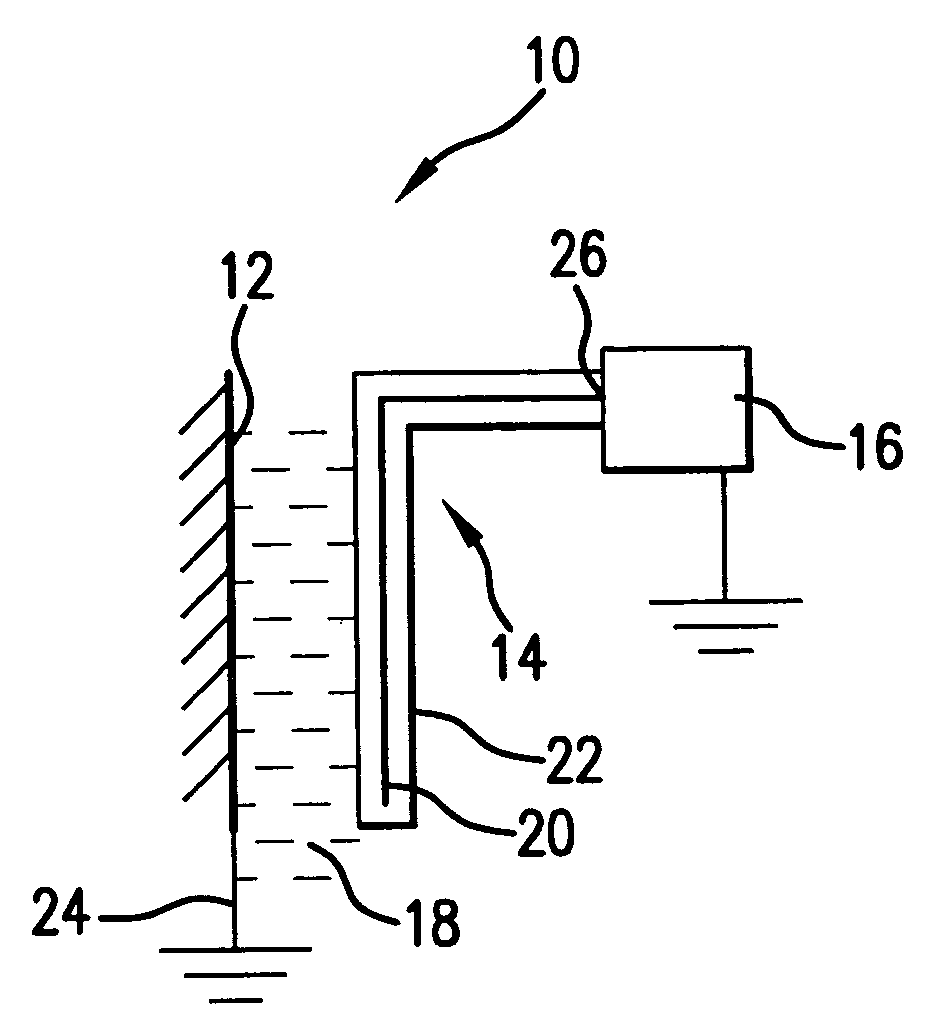
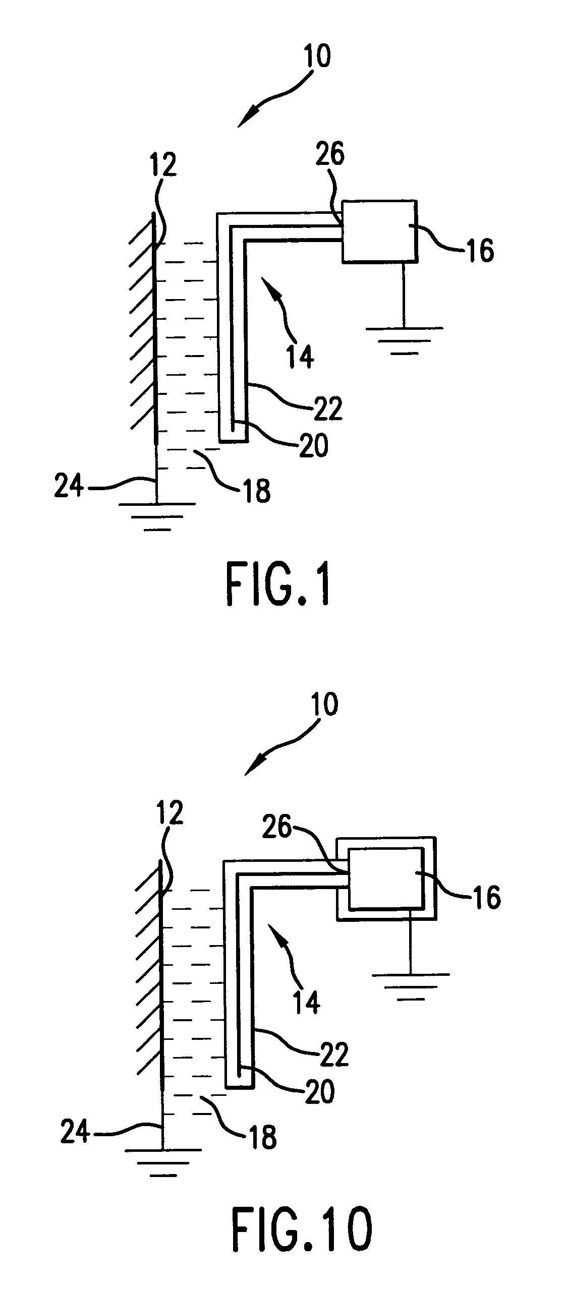
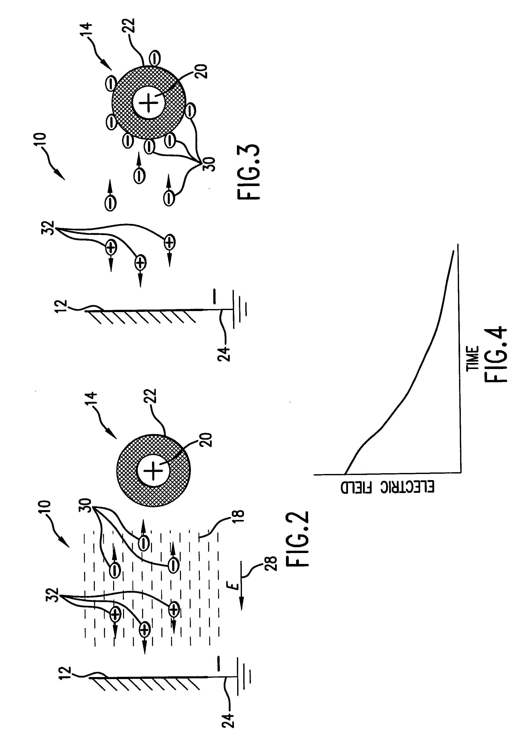
[0064]Referring to FIG. 1, a heat transfer system 10 enhanced by an electrohydrodynamic arrangement, includes a heat transfer surface 12; an encapsulated electrode 14, a high voltage power supply 16, and a dielectric working media 18 in contact with the heat transfer surface 12 and the encapsulated electrode 14. The encapsulated electrode 14 includes an electrode wire 20 (or an electrode plate, not shown in the Drawings) and an insulation layer 22 completely encapsulating the electrode wire 20 up to the high voltage power supply 16. The insulation layer may be formed of Teflon, Kapton, or any other insulating material including surface oxidation compounds.

[0065]The heat transfer surface 12 is coupled to the ground via the ground electrode 24. The high voltage power supply 16 coupled to the end 26 of the encapsulated electrode 14, energizes the encapsulated electrode 14 by either uni-polar or bi-directional pulses of energy. The encapsulated electrode 14 generates a high voltage elec...


PUM

PropertyMeasurementUnit
electric fieldaaaaaaaaaa
heataaaaaaaaaa
voltageaaaaaaaaaa

Abstract

An electrohydrodynamically enhanced heat transfer system (EHD) includes an electrode completely encapsulated in an insulating material and coupled to a power supply to generate an electric field between a heat transfer surface and the encapsulated electrode when energized for interacting with the heat exchange surface and the working media to reduce frost formation on the heat transfer surface and to enhance heat transfer. The power supply may be completely encapsulated and immersed into the working media. In order to reduce accumulation of condensed liquid onto the electrode, the surface of the insulating material of the encapsulated electrode is either covered with a water repellent, or heated a few degrees above the dew point temperature of the air surrounding the heat transfer surface. The encapsulated electrode can be energized by an AC or DC electric field through a controlling switch.

Description

REFERENCE TO RELATED APPLICATION[0001]The current Utility Patent Application is based on Provisional Patent Application #60 / 372,756, filed Apr. 15, 2002.FIELD OF THE INVENTION[0002]The present invention relates to heat and mass transport, and particularly, to electrohydrodynamic (EHD) enhancement of heat and mass transfer.[0003]More specifically, the present invention relates to an EHD enhanced heat and mass transfer technique in which an electrode which couples an electric field to the heat transfer fluid is completely encapsulated in electrically insulating material in order to prevent current leakage and short circuiting between a heat transfer surface and the electrode while enhancing the EHD heat transfer and reducing power consumption for EHD effects, preventing electrochemical corrosion of electrodes, and generating a double electrical field across the working media for sufficient time period while maintaining the electrode at substantially the same potential.[0004]In additio...

Claims


Application Information

Patent Timeline
Patent Type & Authority Patents(United States)
IPC IPC(8): F28F27/00H05K7/20F28F13/16H01M14/00
CPCH01M14/00F28F13/16
Inventor DESSIATOUN, SERGUEI V.IVAKHNENKO, IGOROHADI, MICHAEL M.
Owner UNIV OF MARYLAND
Why Eureka
Try Eureka