Image forming device

a technology of forming device and forming chamber, which is applied in the direction of instruments, electrographic process equipment, optics, etc., can solve the problems of accumulating toner in the vicinity of the toner receiving/supplying portion, and unable to completely prevent toner leakage and accumulation

Inactive Publication Date: 2008-03-13
MURATA MASCH LTD
View PDF3 Cites 16 Cited by
  • Summary
  • Abstract
  • Description
  • Claims
  • Application Information

AI Technical Summary

Benefits of technology

[0010]In order to overcome the problems described above, preferred embodiments of the present invention provide an image forming device in whic

Problems solved by technology

At the toner receiving/supplying portion, since the toner is composed of microscopic particles, toner leakage cannot be completely prevented.
Therefore, it is unavoidable that some of the toner leaks and accumulates in the vicinity of the toner receiving/supplying portion.
However, when changing a toner container cartridge or each process unit, the accumulated toner may scatter due to oscillations and impacts occur on the device body.
As a result, the toner is transferred and adhered to a mechanism portion, which affects the image quality, and the toner can stain the user's clothing or hands.
Because the housing including the cartridge and the process unit is made of resin and metal, the toner accumulated on a surface of the housing is not fixed and can be easily detached by the oscillations and the impacts.
Thus, paper sc

Method used


Image

  • Image forming device
  • Image forming device
  • Image forming device

Examples


Embodiment Construction

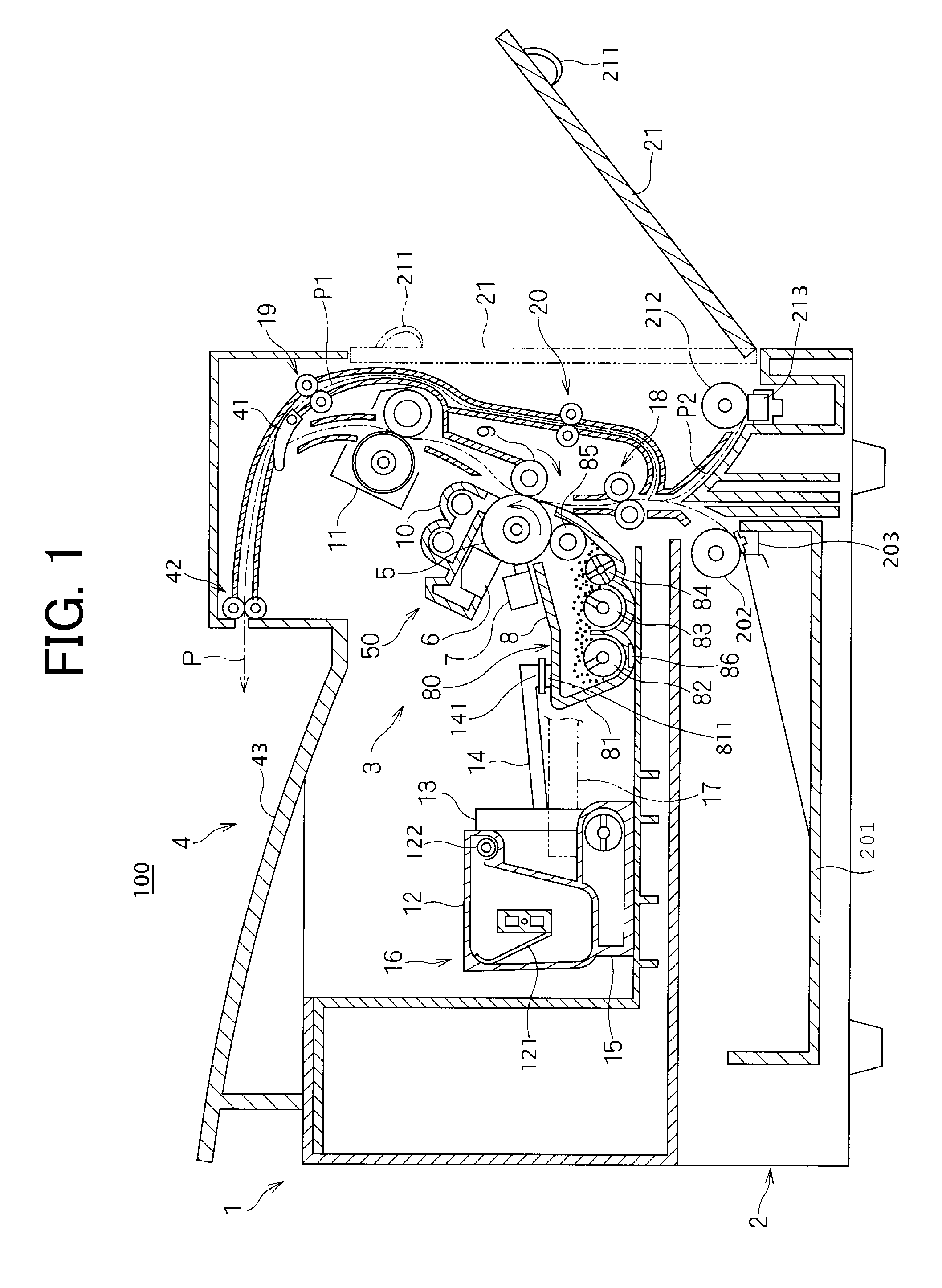
[0020]With reference to the drawings, description will be made of preferred embodiments of the present invention. An image forming device 100 in FIG. 1 is a printer, for example, including an electrophotographic recording unit. The present invention is not limited to such a printer, but may be a copier, a facsimile machine, or an MFP having a copying function, a facsimile function, and / or a printing function, and including an image scanning device. In FIG. 1, a device main body 1 of the image forming device 100 includes a paper feed unit 2 for recording papers, an electrophotographic image recording unit 3, and a discharge unit 4 for the printed recording papers such that the units 2, 3, and 4 are sequentially stacked in a vertical direction. The paper feed unit 2 for the recording papers has a paper feed cassette 201, a paper separating and feeding roller 202, and a separating pad 203. The paper feed cassette 201 can accommodate a plurality of stacked recording papers, and can be r...


PUM


Abstract

An image forming device includes a process unit, a toner containing portion, and a trapping member. The toner containing portion is arranged in relation to the process unit and connected to the process unit so as to define a toner transporting mechanism. The toner transporting mechanism includes a toner receiving/supplying portion having a toner receiving port and a toner supplying port such that the toner receiving port and the toner supplying port can be removably connected to each other. The trapping member is attached to a surface of a portion adjacent to the toner receiving/supplying portion and traps leaked toner.

Description

CROSS-REFERENCE TO RELATED APPLICATIONS[0001]This application claims priority under 35 U.S.C. 119 to Japanese Patent Application No. 2006-246741, filed on Sep. 12, 2006, which application is hereby incorporated by reference in its entirety.BACKGROUND OF THE INVENTION[0002]1. Field of the Invention[0003]The present invention relates to an image forming device.[0004]The image forming device includes an image forming process unit having a developing device, and includes a toner containing portion arranged in relation to the process unit. When the image forming process unit and the toner containing portion are connected, a toner transporting mechanism is established.[0005]2. Description of the Related Art[0006]An electrophotographic image forming device is frequently used in a copier, a facsimile machine, a printer, or a Multi Function Peripheral (MFP) having a copying function, a facsimile function, and / or a printing function. Some of these image forming devices use a developer includi...

Claims


Application Information

Patent Timeline
IPC IPC(8): G03G15/08
CPCG03G21/12G03G2215/0692G03G21/105G03G15/0855G03G15/0886G03G15/0865G03G15/0879G03G21/10G03G21/00
Inventor IKADO, MASAHARUKAWAI, HIDEAKI
Owner MURATA MASCH LTD
Why Eureka
Try Eureka