
Uplink communication method and radio terminal in radio communication system

a radio communication system and communication method technology, applied in connection management, climate sustainability, sustainable buildings, etc., can solve the problems of deterioration of the power consumption efficiency of the ue b>200/, further deterioration of reception quality, etc., to reduce the transmission electric power of the radio terminal and suppress interference with other radio communication equipment.

Inactive Publication Date: 2008-03-13
FUJITSU LTD
View PDF17 Cites 60 Cited by
  • Summary
  • Abstract
  • Description
  • Claims
  • Application Information

AI Technical Summary

Benefits of technology

[0040]In the light of the above problems, an object of the present invention is to control transmission timing of a request for obtaining, from a radio base station, permission to transmit an uplink signal, thereby obtaining an expected throughput and suppress interference with other radio communication equipments while decreasing the transmission electric power of a radio terminal.
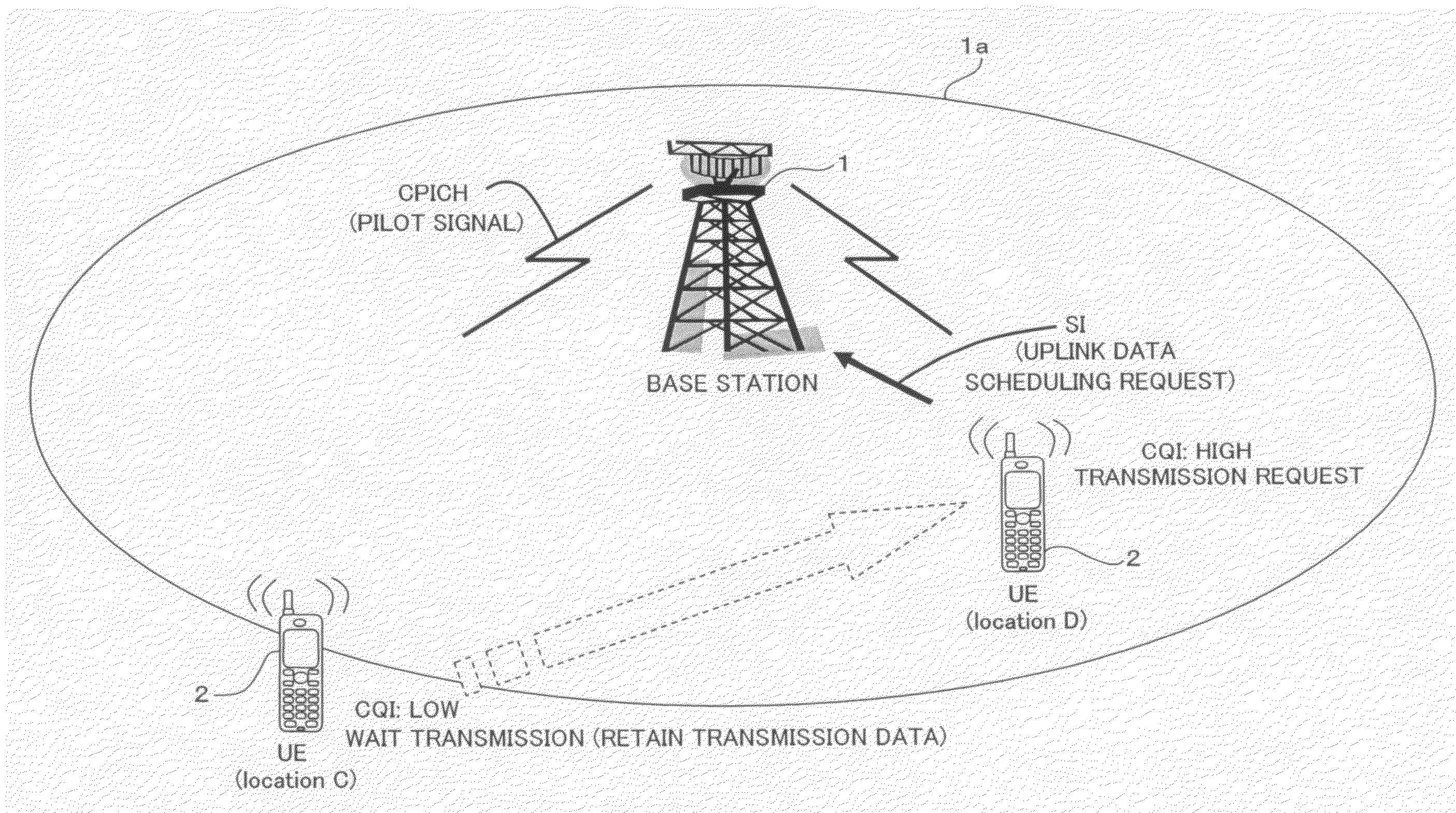
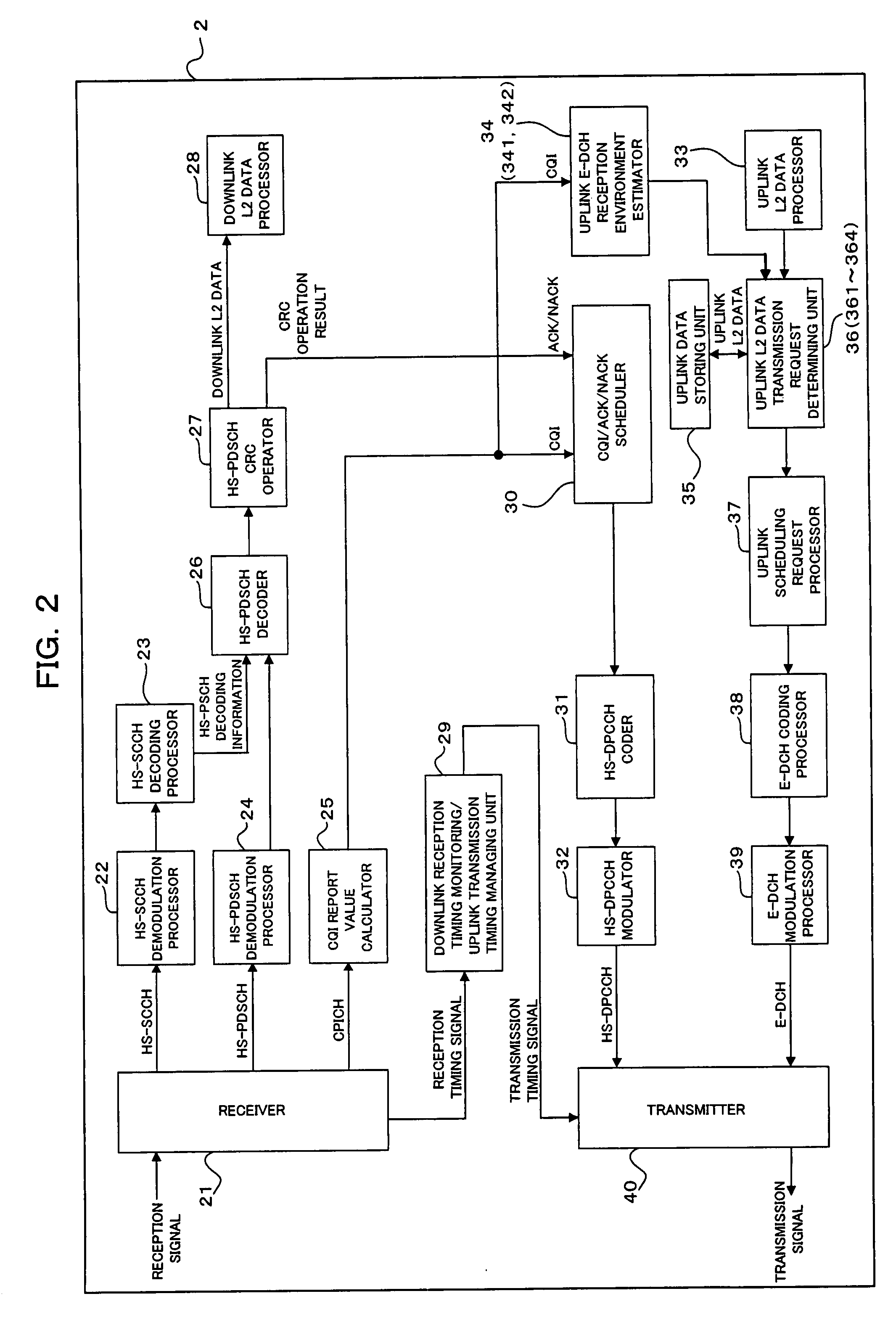
[0051](1) The radio terminal estimates a reception quality of an uplink signal at the radio base station (hereinafter referred to simply as “base station”) based on the downlink signal received from the base station, and controls transmission timing of a transmission request to the base station to obtain permission to transmit the uplink signal based on the result of the estimation. Whereby, transmission of the transmission request of the uplink signal can be waited when reception environments at the base station are estimated to be poor, and the transmission request can be transmitted when the reception environments at the base station are estimated to be good. Accordingly, it is possible to suppress a transmission electric power of the radio terminal to low, obtain an expected throughput, and reduce interference with other radio communication equipments.
[0052](2) A transmission electric power of the current uplink signal is monitored to determine whether to issue the transmission request of the uplink signal according to a result of the monitoring. This enables a reduction in power consumption of the radio terminal.
[0054](4) The transmission timing can be controlled based on input information relating to transmission timing of the transmission request from the user through the inputting unit. Accordingly, it is possible to appropriately change the transmission timing of the transmission request according to convenience (will) of the user, which leads to improvement of utility for the user.
[0055](5) A battery remaining quantity of the radio terminal is monitored, and the smaller the battery remaining quantity, the harder the transmission request is transmitted. This is helpful to further reduce the power consumption of the radio terminal.

Problems solved by technology

In a bad case, the communication is initiated in environments of a poor reception quality, the reception quality is further deteriorated thereafter, and the communication is terminated before the data transmission is completed, after all.
This leads to deterioration of the power consumption efficiency of the UE 200, and causes interference with other radio communication equipments.

Method used


Image

  • Uplink communication method and radio terminal in radio communication system
  • Uplink communication method and radio terminal in radio communication system
  • Uplink communication method and radio terminal in radio communication system

Examples


Embodiment Construction

[0065]Preferred embodiments of the present invention are described in more detail below referring to the accompanying drawings.

[A] Explanation of Outline

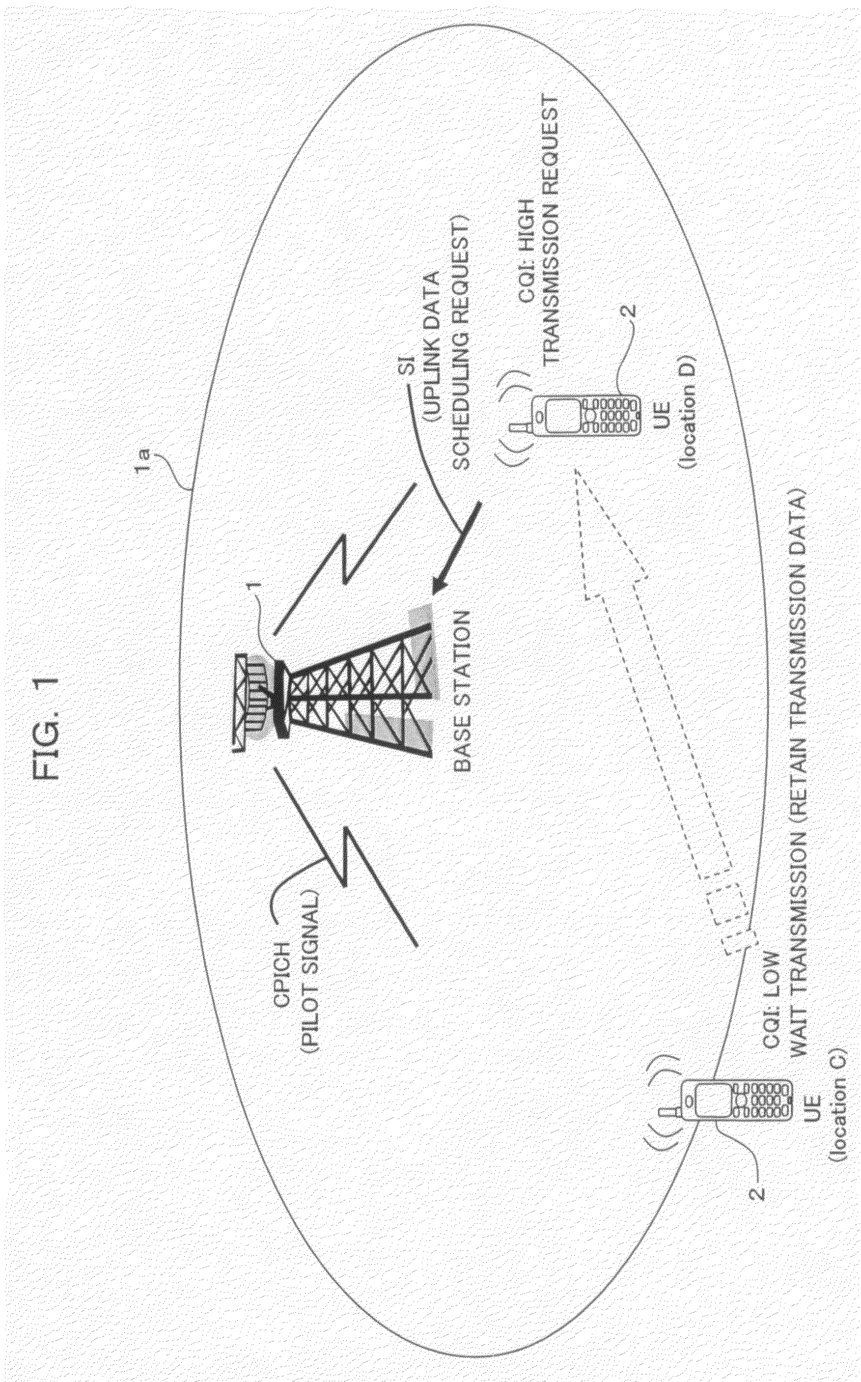
[0066]FIG. 1 is a diagram schematically showing a structure of a mobile communication system according to an embodiment of this invention. The mobile communication system shown in FIG. 1 comprises a radio base station (BTS: Base Transceiver Station) 1, and a mobile station (MS: Mobile Station) as being a radio (user) terminal (UE) such as a cellular phone being capable of radio communication with the BTS 1 within a radio area (cell) 1a formed by the BTS 1. In this embodiment, it is assumed that downlink communication from the BTS 1 to the MS (occasionally referred to as UE) 2 is performed in HSDPA, whereas uplink communication from the MS 2 to the BTS 1 is performed in HSUPA. Incidentally, the number of the BTSs 1 may be one or more, as well as the MSs 2.

[0067]The reception quality at the BTS 1 of transmission data (hereinafter refe...


PUM


Abstract

A radio terminal estimates a reception quality of an uplink signal at a radio base station based on a downlink signal received from the radio base station, and controls transmission timing to the radio base station of a transmission request for obtaining permission to transmit the uplink signal. Whereby, it is possible to control the transmission timing of the request for obtain permission to transmit the uplink signal from the radio base station, decrease a transmission electric power of the radio terminal, and obtain an expected throughput.

Description

CROSS REFERENCE TO RELATED APPLICATION(S)[0001]This application is based on and hereby claims priority to Japanese Application No. 2006-246743 filed on Sep. 12, 2006 in Japan, the contents of which are hereby incorporated by reference.BACKGROUND OF THE INVENTION[0002](1) Field of the Invention[0003]The present invention relates to an uplink communication method and a radio terminal in a radio communication system, and particularly to a technique suitable for use in a radio communication system which performs communications by radio in W-CDMA (Wideband-Code Division Multiple Access).[0004](2) Description of Related Art[0005]W-CDMA is one of radio communication interfaces defined by IMT-2000 (International Mobile Telecommunications-2000), which is in a position of the representative radio communication system.[0006]W-CDMA enables multi-media access of voice, motion pictures, data and so forth at a transmission rate of up to 384 kbps.[0007]Communication systems called HSDPA (High Speed...

Claims


Application Information

Patent Timeline
Patent Type & Authority Applications(United States)
IPC IPC(8): H04Q7/20H04W28/00H04W52/02H04W52/14H04W68/02H04W74/04H04W74/08H04W76/02
CPCH04W52/146Y02B60/50H04W74/0808
Inventor NIBE, KEIJI
Owner FUJITSU LTD
Learn More