Distributor Indexing Device

Inactive Publication Date: 2008-03-13
RAASCH STEPHEN PAUL +1
View PDF1 Cites 3 Cited by
  • Summary
  • Abstract
  • Description
  • Claims
  • Application Information

AI Technical Summary

Benefits of technology

[0010]The device of the present invention has obtained these objects. It provides for a distribution indexing device that is attachable to pin-setting machines of current manufacture. This device allows for the indexing of the distributing mechanism as originally designed and intended. The device of the present invention accomplishes this by allowing for the replacement and elimination of certain mechanical components within the distributing mechanism that are prone to wear and which require constant maintenance. In the preferred embodiment of the present invention, the device includes a drive structure and an electrical contact structure. The drive structure is attachable to the distributing mechanism at a point at which a drive gear engages the indexing gear. The electrical contact structure includes two contacts, one that is attachable to a stationary component of the distributing mechanism and one that is attachable to a moving component of the distributing mechanism. As a pin moves onto and is lowered into the pin magazine by the trip arms, the trip arms cause the movable contact to engage the stationary contact, thus generating an electrical signal to the drive structure. Following a short time delay, the drive structure moves the indexing gear a pre-determined amount such that the indexing cams are allowed to function as intended.

Problems solved by technology

In the experience of these inventors, problems are frequently experienced with use of the friction-drive clutch as identified above.
The friction-drive clutch has been an unreliable system because of many factors.
Ambient temperatures, as well as humidity, along with dirt and grease in the working environment, together with poor housekeeping, are the main reasons for failure of the friction-drive clutch.

Method used


Image

  • Distributor Indexing Device
  • Distributor Indexing Device
  • Distributor Indexing Device

Examples


Embodiment Construction

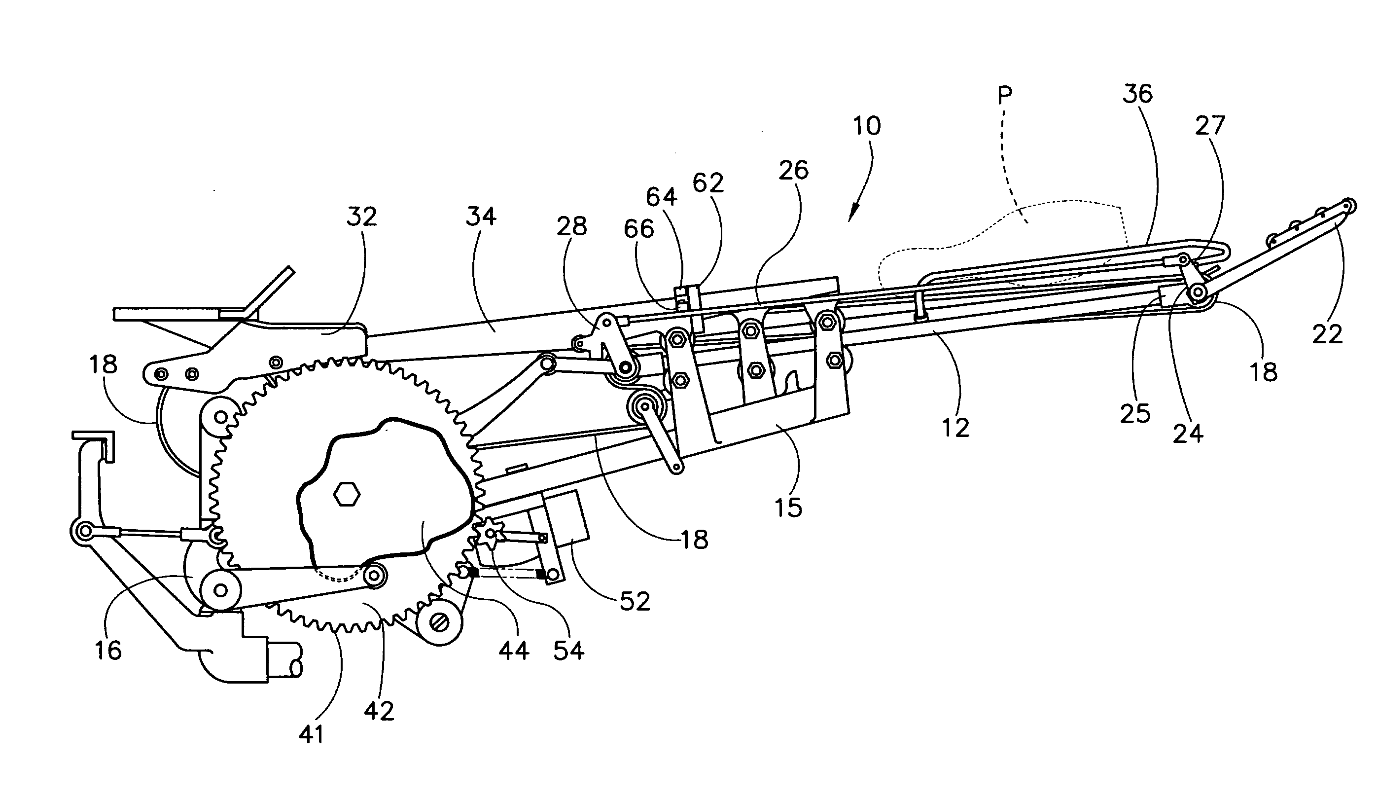
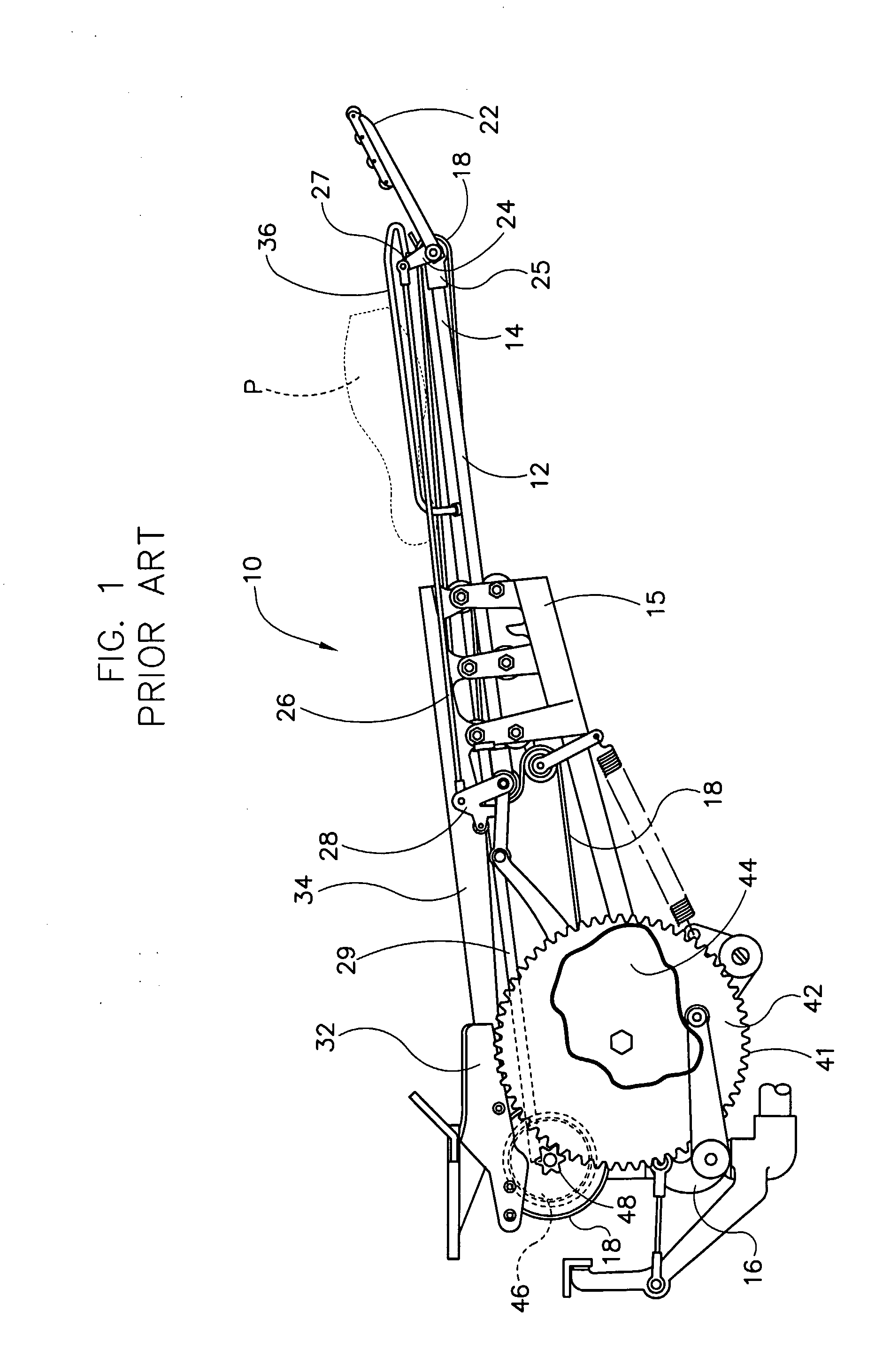
[0017]Referring now to the drawings in detail wherein like numbers represent like elements throughout, FIG. 1 illustrates a side elevational view of a bowling pin distributing mechanism, generally identified 10, that is constructed in accordance with the prior art. The distributing mechanism 10 shown is essentially the same in construction and operation as element D shown in U.S. Pat. No. 3,526,401, which is described in substantially greater detail starting at Col. 3, Line 64 to Col. 7, Line 47 thereof and which is incorporated herein by reference, but with element numbers as assigned herein. For brevity, the essential elements and function of the distributing mechanism 10 will be presented here for purposes of understanding the relation between component parts that remain the same in the preferred embodiment of this invention, as well as those that are replaced by it.

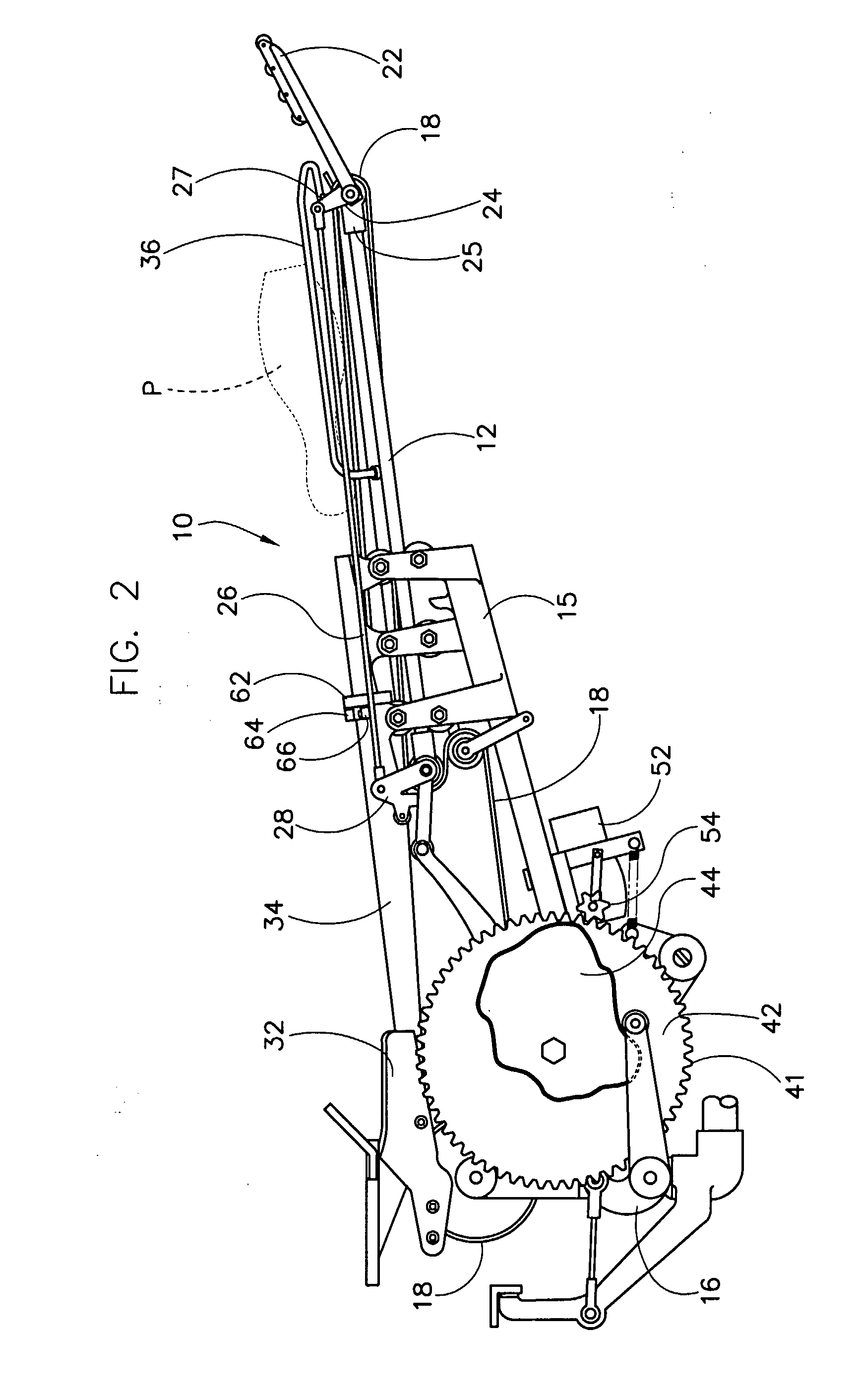
[0018]As shown, the distributing mechanism 10 includes a boom 12 having a proximal portion 16 and a distal portion ...


PUM


Abstract

A distribution indexing device (50, 60) is attachable to bowling pin-setting machines and replaces certain mechanical components within the distributing mechanism (10) that are prone to wear and require constant maintenance. The device (50, 60) includes a drive structure (50) and an electrical contact structure (60). The drive structure (50) is attachable to the distributing mechanism (10) such that a drive gear (54) engages an indexing gear (42). The contact structure (60) includes two contacts (64, 66), one (64) that is attachable to a stationary component (15) of the distributing mechanism (10) and one (66) that is attachable to a moving component (26) of the distributing mechanism (10). As a bowling pin (P) is lowered into a pin magazine (4) by trip arms (22), the arms (22) cause the movable contact (66) to engage the stationary contact (64), thus generating an electrical signal to the drive structure (50). Following a short time delay, the drive structure (50) moves the indexing gear (42) a pre-determined amount such that the indexing cams (44) are allowed to function as intended.

Description

[0001]This invention claims the benefit of, and the priority date of, U.S. Provisional Patent Application No. 60,581,408 filed Jun. 21, 2004.FIELD OF THE INVENTION[0002]This invention relates generally to automatic pin-setting machines used in the sport of bowling. Such machines are also referred to as pin-spotting machines.[0003]The present invention also relates generally to pin distribution systems that are used in such machines for filling a generally triangular-shaped pin storage magazine that is disposed above that portion of the bowling lane where the bowling pins are set or “spotted” after they have been knocked down by a bowling ball. More particularly, it relates to a distribution indexing device, an electromechanical device that can be added to such a machine to replace a portion of the mechanical structure of the pin distribution system and, in particular, the mechanical clutch thereof.BACKGROUND OF THE INVENTION[0004]In the sport of bowling, a bowling lane is provided w...

Claims


Application Information

Patent Timeline
IPC IPC(8): A63D5/08
CPCA63D5/08
Inventor RAASCH, STEPHEN PAULBANY, PAUL ALLEN
Owner RAASCH STEPHEN PAUL
Why Eureka
Try Eureka