Method for sensing and controlling radiation incident on substrate

a radiation incident and substrate technology, applied in the field of methods, can solve the problems of not addressing one of the more important aspects of the state of the curing device, unable to provide an accurate reading for control purposes, and the source can disperse, etc., and achieve the effect of deposited energy density

Inactive Publication Date: 2006-12-21
LIGHTWAVE ENERGY SYST
View PDF13 Cites 2 Cited by
  • Summary
  • Abstract
  • Description
  • Claims
  • Application Information

AI Technical Summary

Benefits of technology

[0014] The present invention provides a dual mode, high-energy point source illuminator utilizing a reflector and an ultraviolet light source with a power source that accurately controls the intensity of the illumination emitted by the source and incident on a working surface. The radiation generated by the radiation source is used for curing a radiation curable material formed on the surface of a substrate. The source is energized by an adjustable power supply controlled by an optical sensor, the energy from the illuminator being focused and concentrated in the proximal end of a fiber optic light guide. The output end of the guide includes a first set of fibers dedicated to delivering the radiation to a surface and a second set of fibers the feedback bundle, for receiving radiation reflected from the coating material in its bundle. The feedback branch connects to the radiation sensor via a filter that blocks undesirable signals.
[0017] The amount of signal reflected back from the part having the cure material formed thereon depends on the absorption / reflectance of the part and the curable material being processed. The present invention provides a technique that eliminates the need to know the properties of the cure material and enables the system to maintain the energy density deposited in the curing material substantially constant, correcting for changes in the system status such as bulb aging, variation in part surface emissitivity and others, thus controlling the amount of energy deposited in the curing volume to any degree of accuracy. The amount of exposure is monitored and controlled by adjusting the power to the bulb to compensate for changes in its output, and changes in the process end as well as monitoring the energy output from the guide.
[0019] This technique eliminates the need to know the emissitivity properties of the cure material by simply using voltage ratios or the ratio of any measurable quantities and enables the apparatus to maintain the bulb output constant, correcting for all curing system changes. Thus, the amount of energy deposited in the curing volume is determined and accurately controlled.

Problems solved by technology

However, they do not address one of the more important aspects of the state of the curing devices, i.e. the delivery of constant energy to a volume of curing material without the need to know the emissivities of the different curing materials.
Again, although the above prior art systems provide certain distinct features, one of the disadvantages is that the radiation generated by the source can disperse to some degree before it reaches the material being cured thus not providing an accurate reading for control purposes.
Similarly, the radiation reflected from the material surface may disperse and thus not provide an accurate sensor reading for control purposes.
Most importantly, it is difficult to measure the amount of energy deposited in a volume directly under the surface of a material to be cured (and thus obtain an indication as to the success of the curing process) since the portion of the energy beam reflected depends on the nature and status of the surface of the material being cured.
Although measurement of surface emissivity could provide a parameter to measure the cure effectiveness, it is difficult to measure.

Method used


Image

  • Method for sensing and controlling radiation incident on substrate
  • Method for sensing and controlling radiation incident on substrate
  • Method for sensing and controlling radiation incident on substrate

Examples


Embodiment Construction

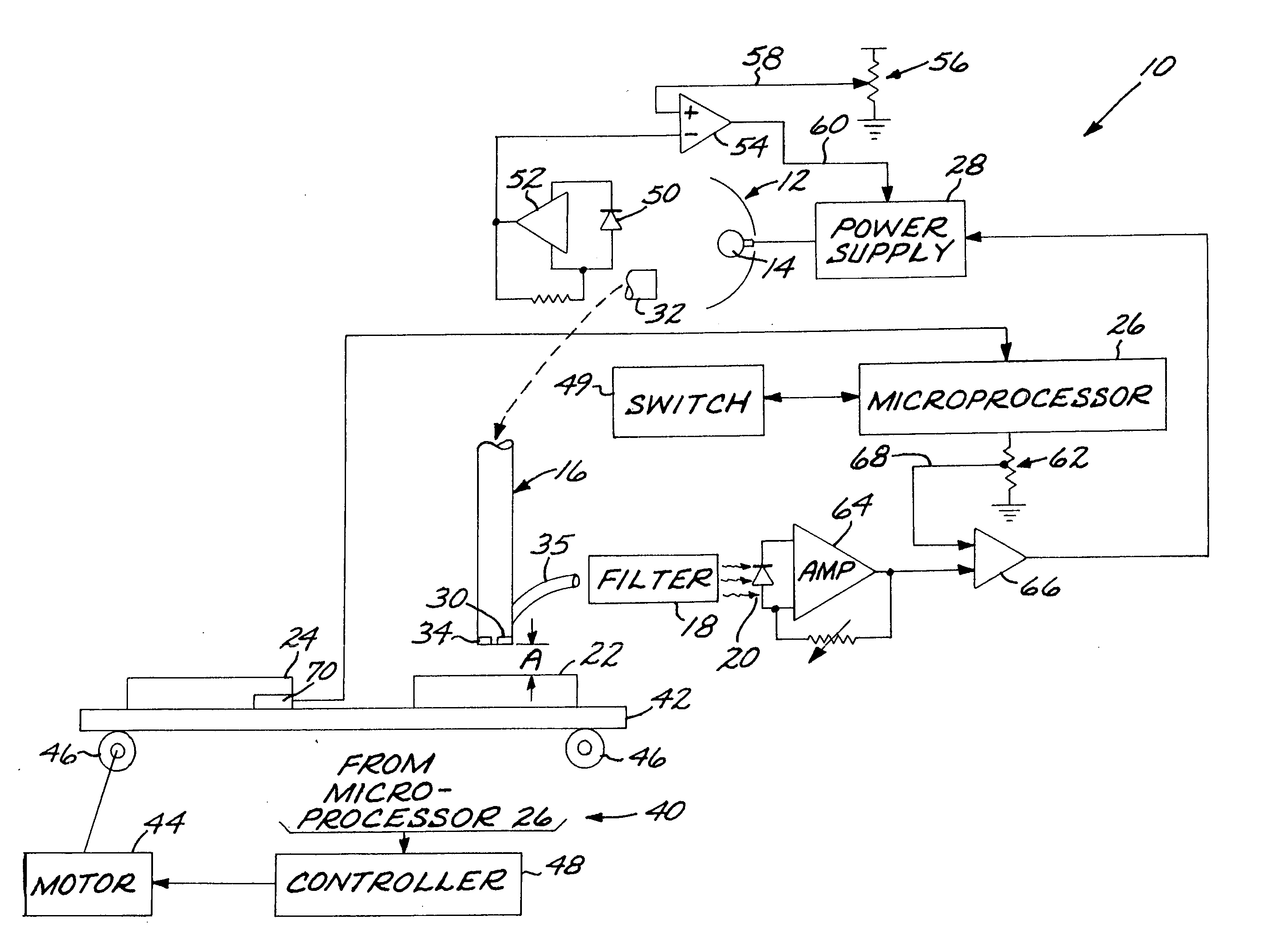
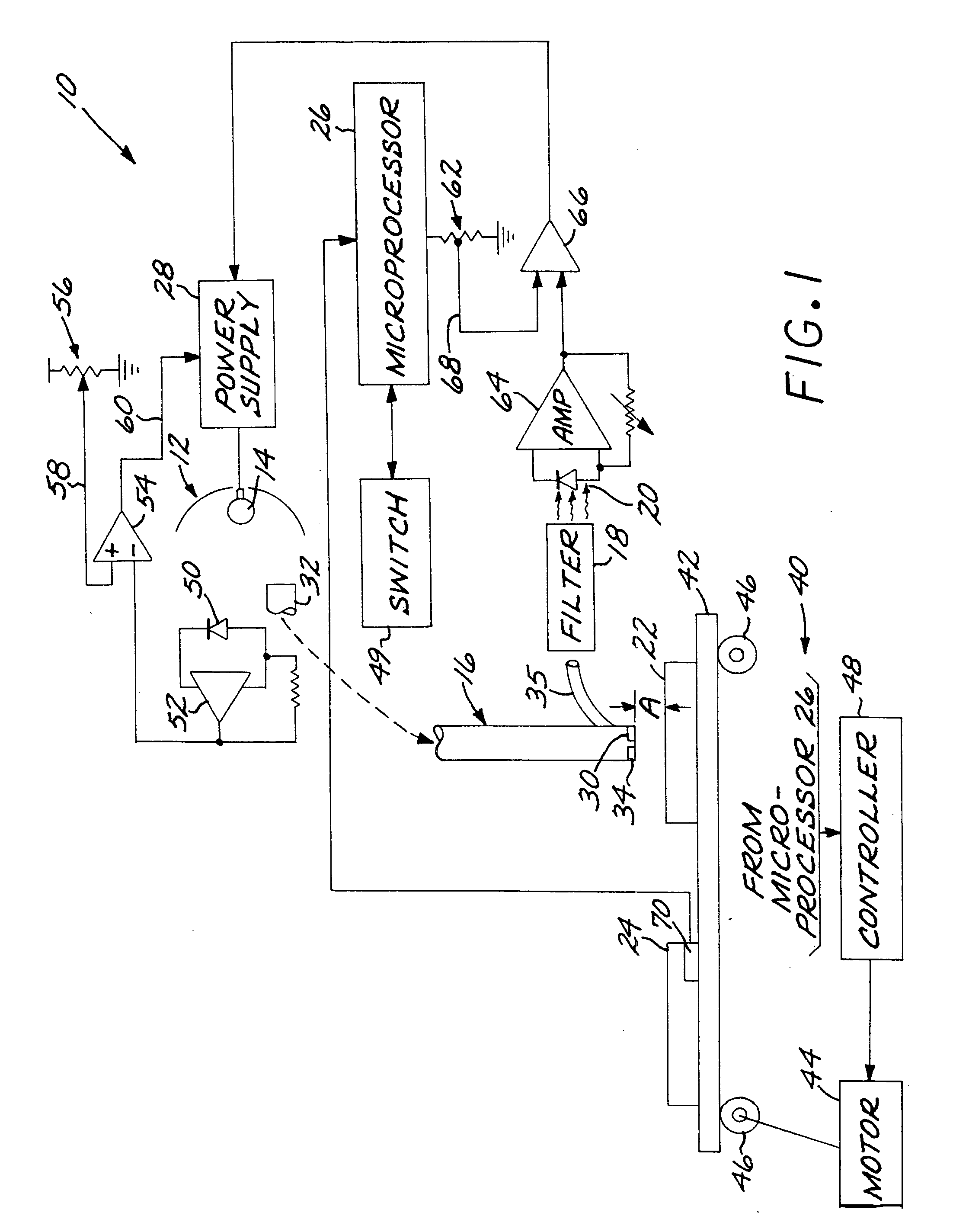
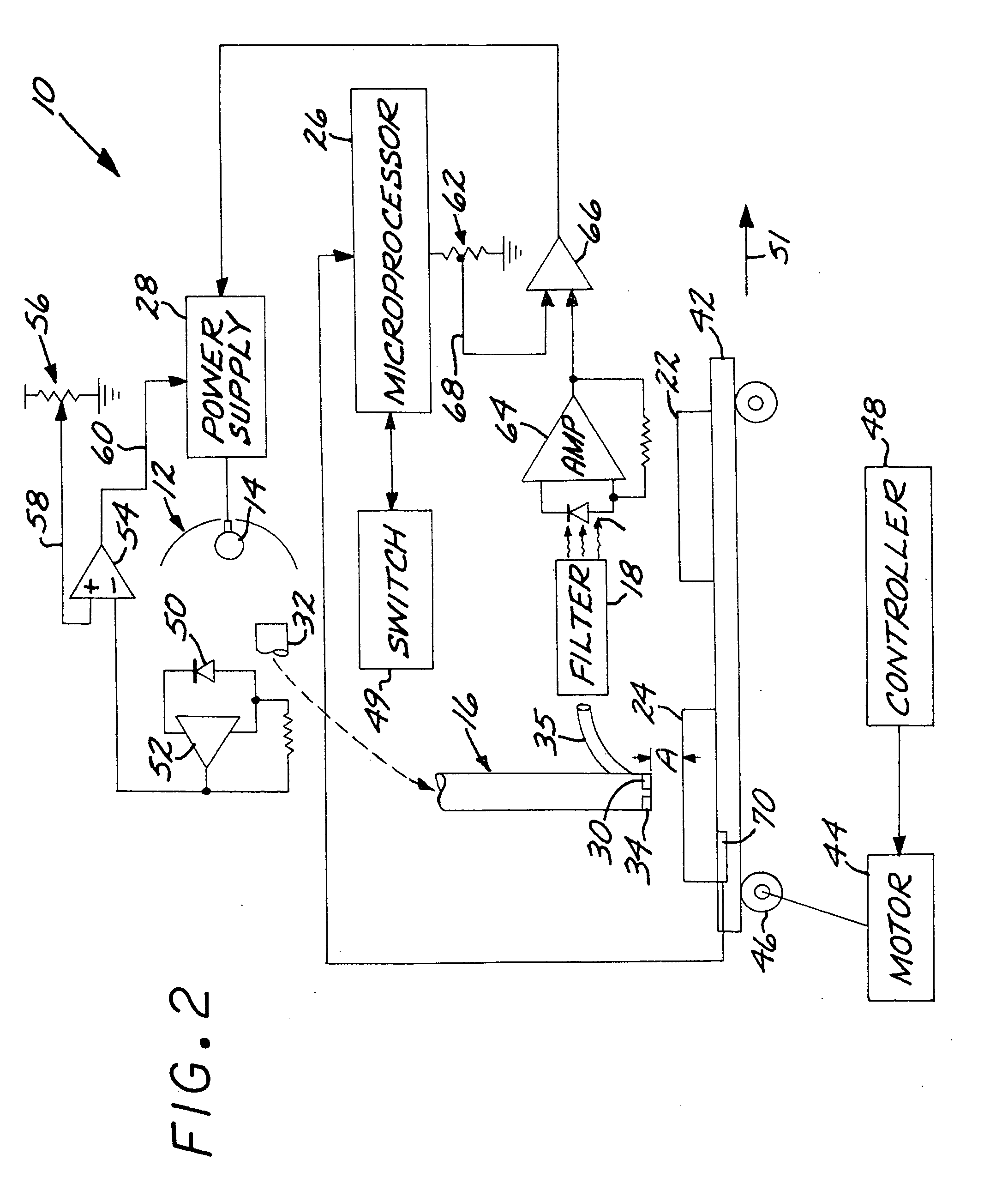
[0024] Referring now to the Figure, the system 10 of the present invention is illustrated in the first, or operating, mode of operation. The components labeled with the same reference numerals in FIGS. 1 and 2 identify identical components. In this example, a UV source or radiation is utilized. However the present invention can be utilized with any other type of radiation field and source.

[0025] The basic components of system 10 comprise of a point source U.V. illuminator 12 having a UV source 14 at the focal point of illuminator 12, fiber optic light guide 16, filter 18, feedback sensor diode 20, working substrate 22, standard substrate 24, microprocessor 26 and power supply 28.

[0026] The fiber optic light guide 16 comprises a distal (output) end 30, a proximal (input) end 32 and a sensing, or feedback, branch 34.

[0027] The UV source 14 is energized by power supply 28, which in turn is controlled by sensor 20.

[0028] The energy from the illuminator 12 is focused and concentrated...


PUM


Abstract

A system is disclosed that is using a high energy point like source illuminator comprising an ultraviolet source, where the source is being energized by a variable power supply that is controlled by a UV sensor and microprocessor. The energy from the illuminator is focused in the proximal end of a fiber optic light guide, a feed back branch coupling reflected light to the UV sensor. The light travels inside the guide and exits through its distal end first exposing a standard substrate. The standard substrate and a working substrate are positioned adjacent to each other and the UV light is first directed toward the standard substrate, the reflected light being incident on the sensor. The sensor output signal is then coupled to the microprocessor, which adjusts the power delivered to the bulb to correspond to the value established for the standard substrate, the microprocessor determining the needed exposure time to affect the cure. Thereafter, the incident light is redirected toward the working substrate, the reflected light therefrom being sensed, the microprocessor then adjusting the power supply such as to keep the bulb light intensity constant in accordance with the parameters established by the standard measurements.

Description

CROSS-REFERENCE TO RELATED APPLICATION [0001] This application is a divisional of application Ser. No. 11 / 007,676, filed Dec. 8, 2004.BACKGROUND OF THE INVENTION [0002] 1. Field of the Invention [0003] The present invention provides a method for setting and controlling the energy emitted from a radiation source that is directed to a volume of material that is to be cured. [0004] 2. Description of the Prior Art [0005] The concept of measuring and / or controlling the output from a source of radiation has been disclosed in the prior art. [0006] For example, systems for controlling the intensity of the output radiation using a feedback arrangement are disclosed in U.S. Pat. Nos. 4,665,627, 5,418,369 and 6,400,444. Systems for controlling the intensity of the output radiation in an open loop mode is disclosed in U.S. Pat. Nos. 6,128,068 and 6,271,909 and systems that measure / control other properties of the radiation are disclosed in U.S. Pat. Nos. 4,848,539, 4,672,196, 4,849,640, 4,865,44...

Claims


Application Information

Patent Timeline
Patent Type & Authority Applications(United States)
IPC IPC(8): G01J1/00
CPCG01J1/0425G01J1/429G01J1/32
Inventor GARCIA, ANDREW J.MOLDOVAN, ANTON G.
Owner LIGHTWAVE ENERGY SYST
Why Eureka
Try Eureka